
Manual


16 DS792F2
CS43L22
Confidential Draft
3/4/10
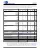
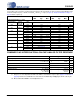
SWITCHING SPECIFICATIONS - SERIAL PORT
Inputs: Logic 0 = DGND; Logic 1 = VL.
11. After powering up the CS43L22, RESET should be held low after the power supplies and clocks are
settled.
12. See “Example System Clock Frequencies” on page 61 for typical MCLK frequencies.
Parameters Symbol Min Max Units
RESET pin Low Pulse Width (Note 11)
1-ms
MCLK Frequency (Note 12) (See “Serial Port Clock-
ing” on page 29)
MHz
MCLK Duty Cycle 45 55 %
Slave Mode
Sample Rate (LRCK) F
s
(See “Serial Port Clock-
ing” on page 29)
kHz
LRCK Duty Cycle 45 55 %
SCLK Frequency 1/t
P
-64•F
s
Hz
SCLK Duty Cycle 45 55 %
LRCK Setup Time Before SCLK Rising Edge t
s(LK-SK)
40 - ns
SDIN Setup Time Before SCLK Rising Edge t
s(SD-SK)
20 - ns
SDIN Hold Time After SCLK Rising Edge t
h
20 - ns
Master Mode
Sample Rate (LRCK) F
s
(See “Serial Port Clock-
ing” on page 29)
Hz
LRCK Duty Cycle 45 55 %
SCLK Frequency SCLK=MCLK mode 1/t
P
- 12.0000 MHz
MCLK=12.0000 MHz 1/t
P
-68•F
s
Hz
all other modes 1/t
P
-64•F
s
Hz
SCLK Duty Cycle 45 55 %
SDIN Setup Time Before SCLK Rising Edge t
s(SD-SK)
20 - ns
SDIN Hold Time After SCLK Rising Edge t
h
20 - ns
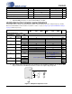
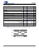
//
//
//
//
//
//
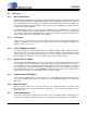
t
s(SD-SK)
MSB MSB-1
LRCK
SCLK
SDIN
t
s(LK-SK)
t
P
t
h
Figure 3. Serial Audio Interface Timing