
Manual


12 DS792F2
CS43L22
Confidential Draft
3/4/10
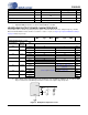
5. See Figure 2. R
L
and C
L
reflect the recommended minimum resistance and maximum capacitance re-
quired for the internal op-amp's stability and signal integrity. In this circuit topology, C
L
will effectively
move the band-limiting pole of the amp in the output stage. Increasing this value beyond the recom-
mended 150 pF can cause the internal op-amp to become unstable.
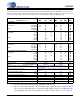
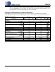
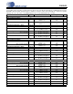
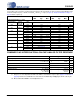
ANALOG PASSTHROUGH CHARACTERISTICS
Test Conditions (unless otherwise specified): Input sine wave (relative to full-scale): 1 kHz through passive input filter;
Passthrough Amplifier and HP/Line Gain = 0 dB; All Supplies = VA; T
A
= +25°C; Sample Frequency = 48 kHz; Measurement
Bandwidth is 20 Hz to 20 kHz.
VA = 2.5 V VA = 1.8 V
Parameters Min Typ Max Min Typ Max Unit
Analog In to HP/Line Amp
R
L
= 10 k
Ω
Dynamic Range A-weighted
unweighted
-
-
-96
-93
-
-
-
-
-94
-91
-
-
dB
dB
Total Harmonic Distortion + Noise -1 dBFS
-20 dBFS
-60 dBFS
-
-
-
-70
-73
-33
-
-
-
-
-
-
-70
-71
-31
-
-
-
dB
dB
dB
Full-scale Input Voltage - 0.91•VA - - 0.91•VA - Vpp
Full-scale Output Voltage - 0.84•VA - - 0.84•VA - Vpp
Passband Ripple - 0/-0.3 - - 0/-0.3 - dB
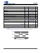
R
L
= 16
Ω
Dynamic Range A-weighted
unweighted
-
-
-96
-93
-
-
-
-
-94
-91
-
-
dB
dB
Total Harmonic Distortion + Noise -1 dBFS
-20 dBFS
-60 dBFS
-
-
-
-70
-73
-33
-
-
-
-
-
-
-70
-71
-31
-
-
-
dB
dB
dB
Full-scale Input Voltage - 0.91•VA - - 0.91•VA - Vpp
Full-scale Output Voltage - 0.84•VA - - 0.84•VA - Vpp
Output Power - 32 - - 17 - mW
Passband Ripple - 0/-0.3 - - 0/-0.3 - dB