
User Manual


40 DS568F1
CS4398
10.PACKAGE DIMENSIONS
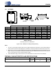
10.1 28-TSSOP
Figure 19. 28L TSSOP (4.4 mm Body) Package Drawing
Notes:
1. “D” and “E1” are reference datums and do not included mold flash or protrusions, but do include mold mis-
match and are measured at the parting line, mold flash or protrusions shall not exceed 0.20 mm per side.
2. Dimension “b” does not include dambar protrusion/intrusion. Allowable dambar protrusion shall be 0.13 mm
total in excess of “b” dimension at maximum material condition. Dambar intrusion shall not reduce dimen-
sion “b” by more than 0.07 mm at least material condition.
3. These dimensions apply to the flat section of the lead between 0.10 and 0.25 mm from lead tips.
THERMAL CHARACTERISTICS AND SPECIFICATIONS
4. θ
JA
is specified according to JEDEC specifications for multi-layer PCBs.
Inches Millimeters Note
DIMMIN NOMMAX MIN NOMMAX
A----0.47----1.20
A1 0.002 0.004 0.006 0.05 0.10 0.15
A2 0.03150 0.035 0.04 0.80 0.90 1.00
b 0.00748 0.0096 0.012 0.19 0.245 0.30 2,3
D 0.378 BSC 0.382 BSC 0.386 BSC 9.60 BSC 9.70 BSC 9.80 BSC 1
E 0.248 0.2519 0.256 6.30 6.40 6.50
E1 0.169 0.1732 0.177 4.30 4.40 4.50 1
e -- 0.026 BSC -- -- 0.65 BSC --
L 0.020 0.024 0.029 0.50 0.60 0.75
µ
0° 4° 8° 0° 4° 8°
JEDEC #: MO-153
Controlling Dimension is Millimeters.
Parameters Symbol Min Typ Max Units
Package Thermal Resistance (Note 4) 28-TSSOP θ
JA
θ
JC
-
-
37
13
-
-
°C/Watt
°C/Watt
E
N
1
23
e
b
2
A1
A2
A
D
SEATING
PLANE
E1
1
L
SIDE VIEW
END VIEW
TOP VIEW
∝