
User Manual


34 DS568F1
CS4398
7.4.5 MUTE Polarity and DETECT (MUTEP1:0) Bits 1-0
Default = 00
00 - Auto polarity detect, selected from AMUTEC pin
01 - Reserved
10 - Active low mute polarity
11 - Active high mute polarity
Function:
Auto mute polarity detect (00)
See section 4.3 on page 20 for description.
Active low mute polarity (10)
When RST
is low, the outputs are high-impedance and will need to be biased active. Once reset has been
released and after this bit is set, the MUTEC output pins will be active low polarity.
Active high mute polarity (11)
At reset time, the outputs are high-impedance and will need to be biased active. Once reset has been
released and after this bit is set, the MUTEC output pins will be active high polarity.
7.5 Channel A Volume Control - Register 05h
7.6 Channel B Volume Control - Register 06h
7.6.1 Digital Volume Control (VOL7:0) Bits 7-0
Default = 00h (0 dB)
Function:
The Digital Volume Control registers allow independent control of the signal levels in 1/2 dB increments
from 0 to -127.5 dB. Volume settings are decoded as shown in Table 7. The volume changes are imple-
mented as dictated by the Soft and Zero Cross bits in the Power and Muting Control register. Note that
the values in the volume setting column in Table 7 are approximate. The actual attenuation is determined
by taking the decimal value of the volume register and multiplying by 6.02/12.
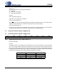
76543210
VOL7 VOL6 VOL5 VOL4 VOL3 VOL2 VOL1 VOL0
00000000
Binary Code Decimal Value Volume Setting
00000000 0 0 dB
00000001 1 -0.5 dB
00000110 6 -3.0 dB
11111111 255 -127.5 dB
Table 7. Example Digital Volume Settings