
Manual

CS4397
DS333F1 17
3.3 MODE SELECT
Mode Control Register (address 01h)
Access:
R/W in I
2
C and SPI.
Default:
00000
Function:
The Mode Select pins determine the operational mode of the device as detailed in Tables 9-14. The op-
tions include:
Selection of the Digital Interface Format which determines the required relationship between the
Left/Right clock, serial clock and serial data as detailed in Figures 29-33
Selection of the standard 15 µs/50 µs digital de-emphasis filter response, Figure 28, which requires re-
configuration of the digital filter to maintain the proper filter response for 32, 44.1 or 48 kHz sample rates.
Selection of the appropriate clocking mode to match the input sample rates.
Access to the Direct Stream Digital Mode
Access to the 8x Interpolation Input Mode
3.4 POWER DOWN
Mode Control Register (address 01h)
Access:
R/W in I
2
C and SPI.
Default:
1 - Powered Down
Function:
The analog and digital sections will be placed into a power-down mode when this function is enabled. This
bit must be cleared to resume normal operation.
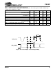
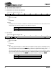
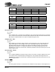
76543210
CAL MUTE
M4 M3 M2 M1 M0 PDN
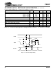
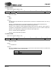
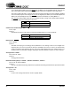
76543210
CAL MUTE
M4 M3 M2 M1 M0 PDN
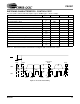
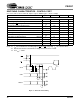
PDN MODE
0 Disabled
1 Enabled
Table 3.