
User guide

CS4392
22 DS459PP3
6.3 Channel A Volume Control - Address 03h
See 4.4 Channel B Volume Control - Address 04h
6.4 CHANNEL B VOLUME CONTROL - ADDRESS 04H
6.4.1 Mute (Bit 7)
Function:
The Digital-to-Analog converter output will mute when enabled. The common mode voltage on the
output will be retained. The muting function is effected, similiar to attenuation changes, by the Soft
and Zero Cross bits in the Volume and Mixing Control register. The MUTEC pin for that channel will
go active during the mute period if the Mute function is enabled. Both the AMUTEC and BMUTEC
will go active if either MUTE register is enabled and the MUTEC A = B bit (register 5) is enabled.
6.4.2 Volume Control (Bits 6:0)
Function:
The digital volume control allows the user to attenuate the signal in 1 dB increments from 0 to -127 dB.
Volume settings are decoded as shown in Table 14. The volume changes are implemented as dictated
by the Soft and Zero Cross bits in the Volume and Mixing Control register (see section 6.2.2).
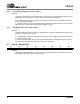
6.5 Mode Control 2 - Address 05h
6.5.1 Invert Signal Polarity (Bits 7:6)
Function:
When set to 1, this bit inverts the signal polarity for the appropriate channel. This is useful if a board
layout error has occurred, or an other situations where a 180 degree phase shift is desirable. Default
is 0.
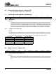
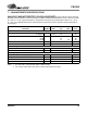
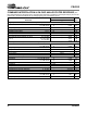
76543210
MUTE VOL6 VOL5 VOL4 VOL3 VOL2 VOL1 VOL0
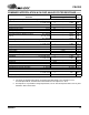
Binary Code Decimal Value Volume Setting
0000000 0 0 dB
0010100 20 -20 dB
0101000 40 -40 dB
0111100 60 -60 dB
1011010 90 -90 dB
Table 14. Digital Volume Control Example Settings
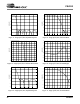
76543210
INVERT_A INVERT_B CPEN PDN MUTEC A = B FREEZE MCLKDIV2 Reserved