
User guide

CS4392
18 DS459PP3
6. REGISTER DESCRIPTION
** All registers are read/write in Two-Wire mode and write only in SPI mode, unless otherwise noted**
6.1 Mode Control 1 - Address 01h
6.1.1 Auto-Mute (Bit 7)
Function:
The Digital-to-Analog converter output will mute following the reception of 8192 consecutive audio
samples of static 0 or -1. A single sample of non-static data will release the mute. Detection and
muting is done independently for each channel. (However, Auto-Mute detection and muting can be-
come dependent on either channel if the Mute A = B function is enabled.) The common mode on the
output will be retained and the Mute Control pin for that channel will go active during the mute period.
The muting function is effected, similar to volume control changes, by the Soft and Zero Cross bits in
the Volume and Mixing Control register.
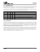
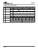
6.1.2 Digital Interface Formats (Bits 6:4)
Function:
PCM Mode - The required relationship between the Left/Right clock, serial clock and serial data is
defined by the Digital Interface Format and the options are detailed in Table 8 and Figures 4-6.
76543210
AMUTE DIF2 DIF1 DIF0 DEM1 DEM0 FM1 FM0
DIF2 DIF1 DIFO DESCRIPTION Format Figure
0 0 0 Left Justified, up to 24-bit data (default) 0 4
001
I
2
S, up to 24-bit data
15
0 1 0 Right Justified, 16-bit Data 2 6
0 1 1 Right Justified, 24-bit Data 3 6
1 0 0 Right Justified, 20-bit Data 4 6
1 0 1 Right Justified, 18-bit Data 5 6
110 Reserved
111 Reserved
Table 8. Digital Interface Formats - PCM Modes