
User guide

CS4392
DS459PP3 11
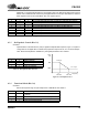
3.6 Digital Interface Format
The device will accept audio samples in several digital interface formats as illustrated in Tables 5 and 8.
The desired format is selected via the M0 and M1 pins for stand alone mode, and through the DIF2:0 bits
in the control port. For an illustration of the required relationship between the Left/Right Clock, Serial
Clock and Serial Audio Data, see Figures 4-6.
M1 M0 DESCRIPTION FORMAT FIGURE
00
Left Justified, up to 24-bit data
04
01
I
2
S, up to 24-bit data
15
10
Right Justified, 16-bit Data
26
11
Right Justified, 24-bit Data
36
Table 5. Digital Interface Format, Stand-Alone Mode Options
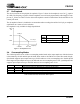
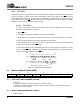
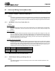
Figure 4. Format 0, Left Justified up to 24-Bit Data
LRCK
SCLK
Left Channel
Right Channel
SDATA +3 +2 +1
LSB
+5 +4
MSB
-1 -2 -3 -4 -5
+3 +2 +1
LSB
+5 +4
MSB
-1 -2 -3 -4
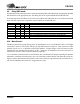
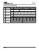
Figure 5. Format 1, I
2
S up to 24-Bit Data
LRCK
SCLK
Left Channel
Right Channel
SDATA +3 +2 +1
LSB
+5 +4
MSB
-1 -2 -3 -4 -5
+3 +2 +1
LSB
+5 +4
MSB
-1 -2 -3 -4
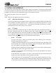
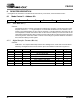
LRCK
SCLK
Left Channel
SDATA
+5
+4 +3 +2
+1
LSB
MSB -1 -2 -3 -4 -5
32 clocks
Right Channel
LSB +5
+4 +3 +2
+1
LSB
MSB
-1 -2 -3 -4
-5
+6
-6
+6
-6
Figure 6. Format 2, Right Justified 16-Bit Data
Format 3, Right Justified 24-Bit Data
Format 4, Right Justified 20-Bit Data. (Available in Control Port Mode only)
Format 5, Right Justified 18-Bit Data. (Available in Control Port Mode only)