
Manual

DS618F2 27
CS4382A
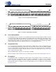
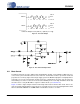
4.11 Mute Control
The Mute Control pins go active during power-up initialization, muting, or if the MCLK-to-LRCK ratio is in-
correct. These pins are intended to be used as control for external mute circuits to prevent the clicks and
pops that can occur in any single-ended, single-supply system. The MUTEC output pins are high impedance
at the time of reset. The external mute circuitry needs to be self biased into an active state in order to be
muted during reset. Once reset has been released, the MUTEC pins are active high in hardware mode and
the active state is set by the MUTEC+/- register in software mode (see Section 6.3.4).
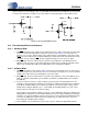
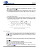
Figure 17 shows a single example of both an active high and an active low mute drive circuit. In these de-
signs, the pull-up and pull-down resistors have been especially chosen to meet the input high/low threshold
when used with the MMUN2111 and MMUN2211 internal bias resistances of 10 k
Ω.
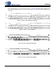
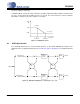
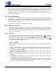
AOUT+
AOUT-
Full-Scale Output Level= (AOUT+) - (AOUT-)= 6.7 Vpp
3.85 V
2.5 V
1.15 V
3.85 V
2.5 V
1.15 V
Figure 15. Full-Scale Output
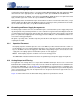
Figure 16. Recommended Output Filter