
Manual

DS618F2 11
CS4382A
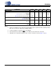
POWER AND THERMAL CHARACTERISTICS
Notes:
4. Current consumption increases with increasing FS within a given speed mode and is signal-dependent.
Max values are based on highest FS and highest MCLK.
5. I
LC
measured with no external loading on the SDA pin.
6. Power-down Mode is defined as RST
pin = Low with all clock and data lines held static.
7. Valid with the recommended capacitor values on FILT+ and VQ as shown in Figures 5 and 6.
Parameters Symbol Min Typ Max Units
Power Supplies
Power Supply Current Normal Operation, VA= 5 V
(Note 4) VD= 2.5 V
(Note 5) Interface Current, VLC=5 V
VLS=5 V
(Note 6) Power-down State (all supplies)
I
A
I
D
I
LC
I
LS
I
pd
-
-
-
-
-
84
20
2
75
200
91
25
-
-
-
mA
mA
µA
µA
µA
Power Dissipation (Note 4) VA = 5V, VD = 2.5V
Normal Operation
(Note 6) Power-down
-
-
470
1
520
-
mW
mW
Package Thermal Resistance Multi-layer
Two-layer
θ
JA
θ
JA
θ
JC
-
-
-
48
65
15
-
-
-
°C/Watt
°C/Watt
°C/Watt
Power Supply Rejection Ratio (Note 7) (1 kHz)
(60 Hz)
PSRR
-
-
60
40
-
-
dB
dB