
Manual

CS4373A
6 DS699F2
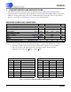
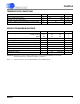
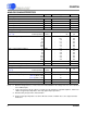
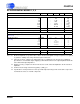
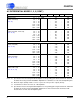
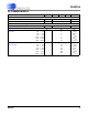
ANALOG CHARACTERISTICS
Notes: 6. Maximum integrated noise over the measurement bandwidth for the voltage reference device attached
to the VREF
± inputs.
7. Load on the precision OUT
± outputs is normally from the CS3301A / CS3302A amplifiers, which have
1GΩ/1 TΩ typical input impedance and 18 pF typical input capacitance.
8. Guaranteed by design and/or characterization.
9. Single-ended output impedance at 1/64 is different for BUF+ and BUF- due to the output attenuator
architecture.
Parameter Symbol Min Typ Max Unit
VREF Input
{VREF+} - {VREF-} (Note 2, 3) VREF - 2.500 - V
VREF- (Note 4)VREF- - VA- - V
VREF Input Current, AC modes VREF
IAC
-80- µA
VREF Input Current, DC modes VREF
IDC
-40- µA
VREF Input Noise (Note 6)VREF
IN
--1µV
rms
Analog OUT± Output
Analog External Load at OUT
± Load Resistance
(Note 7, 8) Load Capacitance
R
LOUT
C
LOUT
50
-
-
-
-
50
MΩ
pF
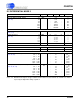
Differential Output Impedance 1/1
1/2
1/4
1/8
1/16
1/32
1/64
ZDIF
OUT
-
-
-
-
-
-
-
1.4
10.1
7.9
5.1
3.3
2.3
1.7
-
-
-
-
-
-
-
kΩ
kΩ
kΩ
kΩ
kΩ
kΩ
kΩ
Single-ended Output Impedance 1/1
1/2
1/4
1/8
1/16
1/32
1/64
ZSE
OUT
-
-
-
-
-
-
-
0.7
7.4
9.0
9.4
9.5
9.5
9.4
-
-
-
-
-
-
-
kΩ
kΩ
kΩ
kΩ
kΩ
kΩ
kΩ
High-Z Impedance (Note 8)HZ
OUT
-3- MΩ
Crosstalk to BUF
± High-Z Output (Note 8)
XT
OUT
--120- dB
Analog BUF± Output
Analog External Load at BUF
± Load Resistance
(Note 8) Load Capacitance
R
LBUF
C
LBUF
1
-
-
-
-
2
kΩ
nF
Differential Output Impedance 1/1 - 1/64 ZDIF
BUF
-6- Ω
Single-ended Output Impedance 1/1 - 1/32
(Note 9) (BUF-) 1/64
(Note 9) (BUF+) 1/64
ZSE
BUF
-
-
-
3
3
50
-
-
-
Ω
High-Z Impedance (Note 8)HZ
BUF
-4.5- MΩ
Crosstalk to OUT
± High-Z Output (Note 8)
XT
BUF
--120- dB