
User Manual


34 DS617F2
CS4362A
6.1.5 Power Down (PDN)
Default = 1
0 - Disabled
1 - Enabled
Function:
The entire device will enter a low-power state when this function is enabled, and the contents of the control
registers are retained in this mode. The power-down bit defaults to ‘enabled’ on power-up and must be
disabled before normal operation in Control Port Mode can occur.
6.2 Mode Control 2 (Address 02h)
6.2.1 Digital Interface Format (DIF)
Default = 000 - Format 0 (Left-Justified, up to 24-bit dat a)
Function:
These bits select the interface format for the serial audio input. The Functional Mode bits determine
whether PCM or DSD Mode is selected.
PCM Mode: The required relationship between the Left/Right clock, serial clock and serial da ta is defined
by the Digita l Interface Format and the options are detailed in Figures 7-12.
Note: While in PCM Mode, the DIF bits shou ld only be chang ed when the power-do wn (PDN) bit is set
to ensure proper switching from one mode to another.
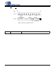
76543210
Reserved DIF2 DIF1 DIF0 Reserved Reserved Reserved Reserved
00000000
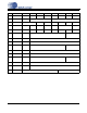
DIF2 DIF1 DIF0 DESCRIPTION Format FIGURE
0 0 0 Left-Justified, up to 24-bit data 0 7
0 0 1 I²S, up to 24-bit data 1 8
0 1 0 Right-Justified, 16-bit data 2 9
0 1 1 Right-Justified, 24-bit data 3 10
1 0 0 Right-Justified, 20-bit data 4 11
1 0 1 Right-Justified, 18-bit data 5 12
1 1 0 Reserved -
1 1 1 Reserved -
Table 5. Digital Interface Formats - PCM Mode