
User Manual


DS617F2 27
CS4362A
4.11 Mute Control
The Mute Control pins go active during power-up initialization, muting, or if the MCLK-to-LRCK ratio is in-
correct. These pins are intended to be used as control for external mute circuits to prevent the clicks and
pops that can occur in any single-ended, single-supply system. The MUTEC output pins are high impedance
at the time of reset. The external mute circuitry ne eds to be self biased int o an active state in order to be
muted during reset. Once reset has been rele ased, the MUTEC pins are active high in hardware m ode and
the active state is set by the MUTEC+/- register in software mode (see Section 6.3.4).
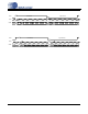
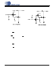
Figure 17 shows a single example of both an active high and an active low mute drive circuit. In these de-
signs, the pull-up and pull-down resistors have bee n especially chosen to meet the input high/lo w threshold
when used with the MMUN 2111 and MMUN2211 intern a l bias resistances of 10 k
Ω.
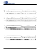
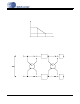
AOUT+
AOUT-
Full-Scale Output Level= (AOUT+) - (AOUT-)= 6.7 Vpp
3.85 V
2.5 V
1.15 V
3.85 V
2.5 V
1.15 V
Figure 15. Full-Scale Output
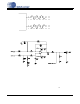
Figure 16. Recommended Output Filter