
User Manual

DS617F2 15
CS4362A
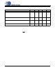
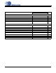
SWITCHING CHARACTERISTICS - PCM
(Inputs: Logic 0 = GND, Logic 1 = VLS, C
L
= 30 pF)
Notes:
14. After powering up, RST
should be held low until after the power supplies and clocks are settled.
15. See Table 1 on page 21 for suggested MCLK frequencies.
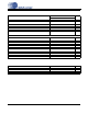
Parameters Symbol Min Max Units
RST pin Low Pulse Width (Note 14) 1-ms
MCLK Frequency 1.024 55.2 MHz
MCLK Duty Cycle (Note 15) 45 55 %
Input Sample Rate - LRCK Single-speed Mode
Double-speed Mode
Quad-speed Mode
F
s
F
s
F
s
4
50
100
54
108
216
kHz
kHz
kHz
LRCK Duty Cycle 45 55 %
SCLK Duty Cycle 45 55 %
SCLK High Time t
sckh
8-ns
SCLK Low Time t
sckl
8-ns
LRCK Edge to SCLK rising edge t
lcks
5-ns
SDIN Setup Time before SCLK rising edge t
ds
3-ns
SDIN Hold Time af ter SCLK rising edge t
dh
5-ns
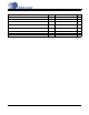
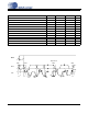
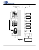
SDINx
t
ds
SCLK
LRCK
MSB
t
dh
t
sckh
t
sckl
t
lcks
MSB-1
Figure 1. Serial Audio Interface Timing