
User Manual

12 DS617F2
CS4362A
COMBINED INTERPOLATION & ON-CHIP ANALOG FILTER RESPONSE
The filter charact er istics have been norm a lized to th e sample rate (Fs) and can be referenced to the desired sam-
ple rate by multiplying the given characteristic by Fs.
See Note 12.
Notes:
8. Slow roll-off interpolation filter is only available in Software Mode.
9. Response is clock-dependent and will scale with Fs.
10. For Single-Speed Mode, the Measurement Bandwidth is from stopband to 3 Fs.
For Double-Speed Mode, the Measurement Bandwidth is from stopband to 3 Fs.
For Quad-Speed Mode, the Measurement Bandwidth is from stopband to 1.34 Fs.
11. De-emphasis is available only in Single-Speed Mode; only 44.1 kHz De-emphasis is available in Hard-
ware Mode.
12. Amplitude vs. Frequency plots of this data are available in Section 7. “Filter Plots” on page 42.
Parameter
Fast Roll-Off
UnitMin Typ Max
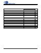
Combined Digital and On -chip Analog Filter Response - Single-Speed Mode - 48 kHz
Passband (Note 9) to -0.01 dB corner
to -3 dB corner
0
0
-
-
.454
.499
Fs
Fs
Frequency Response 10 Hz to 20 kHz -0.01 - +0.01 dB
St op Band 0.547 - - Fs
Stop-band Attenuation (Note 10) 102 - - dB
Group Delay - 10.4/Fs - s
De-emphasis Error (Note 11) Fs = 32 kHz
(Relative to 1 kHz) Fs = 44.1 kHz
Fs = 48 kHz
-
-
-
-
-
-
±0.23
±0.14
±0.09
dB
dB
dB
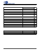
Combined Digital and On-chip Analog Filter Response - Double-Speed Mode - 96 kHz
Passband (Note 9) to -0.01 dB corner
to -3 dB corner
0
0
-
-
.430
.499
Fs
Fs
Frequency Response 10 Hz to 20 kHz -0.01 - +0.01 dB
Stop Band .583 - - Fs
Stop-band Attenuation (Note 10) 80 - - dB
Group Delay - 6.15/Fs - s
Combined Digital and On-chip Analog Filter Response - Quad-Speed Mode - 192 kHz
Passband (Note 9) to -0.01 dB corner
to -3 dB corner
0
0
-
-
.105
.490
Fs
Fs
Frequency Response 10 Hz to 20 kHz -0.01 - +0.01 dB
Stop Band .635 - - Fs
Stop-band Attenuation (Note 10) 90 - - dB
Group Delay - 7.1/Fs - s