
Manual

DS257F2 9
CS4362
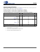
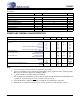
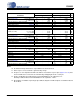
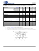
SWITCHING CHARACTERISTICS
(For KQZ T
A
= -10°C to +70°C; VLS = 1.8 V to 5.5 V; Inputs: Logic 0 = GND, Logic 1 = VLS, C
L
= 30 pF)
Notes:
15. See Table 5 on page 27 for suggested MCLK frequencies
16. This serial clock is available only in Control Port Mode when the MCLK Divide bit is enabled.
17. The higher frequency LRCK must be an exact integer multiple (1, 2, or 4) of the lower frequency LRCK
.
Parameters Symbol Min Typ Max Units
MCLK Frequency (Note 15)
Single-Speed Mode 1.024 - 51.2 MHz
Double-Speed Mode 6.400 - 51.2 MHz
Quad-Speed Mode 6.400 - 51.2 MHz
MCLK Duty Cycle 405060%
Input Sample Rate Single-Speed Mode
Double-Speed Mode
Quad-Speed Mode
Fs
Fs
Fs
4
50
100
-
-
-
50
100
200
kHz
kHz
kHz
LRCK Duty Cycle 45 50 55 %
SCLK Pulse Width Low t
sclkl
20 - - ns
SCLK Pulse Width High t
sclkh
20 - - ns
SCLK Period
t
sclkw
--ns
(Note 16)
t
sclkw
--ns
SCLK rising to LRCK edge delay t
slrd
20 - - ns
SCLK rising to LRCK edge setup time t
slrs
20 - - ns
SDATA valid to SCLK rising setup time t
sdlrs
20 - - ns
SCLK rising to SDATA hold time t
sdh
20 - - ns
LRCK1 to LRCK2 frequency ratio (Note 17) 0.25 1.00 4.00
2
MCLK
-----------------
4
MCLK
-----------------
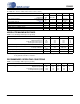
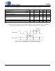
sclkh
t
slrs
t
slrd
t
sdlrs
t
sdh
t
sclkl
t
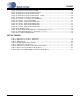
SDATA
SCLK
LRCK
Figure 1. Serial Mode Input Timing