
Instruction Manual

7
CS4361
Confidential Draft
9/30/11
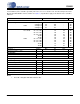
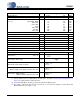
COMBINED INTERPOLATION & ON-CHIP ANALOG FILTER RESPONSE
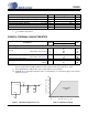
The filter characteristics have been normalized to the sample rate (Fs) and can be referenced to the desired sam-
ple rate by multiplying the given characteristic by Fs. (See Note 5)
2. Response is clock-dependent and will scale with Fs.
3. For Single-Speed Mode, the measurement bandwidth is 0.5465 Fs to 3 Fs.
For Double-Speed Mode, the measurement bandwidth is 0.577 Fs to 1.4 Fs.
For Quad-Speed Mode, the measurement bandwidth is 0.7 Fs to 1 Fs.
4. De-emphasis is available only in Single-Speed Mode.
5. Amplitude vs. Frequency plots of this data are available in “Performance Plots” on page 18.
Parameter Symbol Min Typ Max Unit
Single-Speed Mode
Passband (Note 2) to -0.05 dB corner
to -3 dB corner
0
0
-
-
.4780
.4996
Fs
Fs
Frequency Response 10 Hz to 20 kHz -.01 - +.08 dB
StopBand .5465 - - Fs
StopBand Attenuation (Note 3) 50 - - dB
Group Delay tgd - 10/Fs - s
De-emphasis Error (Note 4) Fs = 44.1 kHz - - +.05/-.25 dB
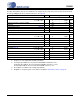
Double-Speed Mode
Passband (Note 2) to -0.1 dB corner
to -3 dB corner
0
0
-
-
.4650
.4982
Fs
Fs
Frequency Response 10 Hz to 20 kHz -.05 - +.2 dB
StopBand .5770 - - Fs
StopBand Attenuation (Note 3) 55 - - dB
Group Delay tgd - 5/Fs - s
Quad-Speed Mode
Passband (Note 2) to -0.1 dB corner
to -3 dB corner
0
0
-
-
0.397
0.476
Fs
Fs
Frequency Response 10 Hz to 20 kHz 0 - +0.00004 dB
StopBand 0.7 - - Fs
StopBand Attenuation (Note 3) 51 - - dB
Group Delay tgd - 2.5/Fs - s