
User Manual


CS4360
DS517F2 17
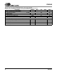
SWITCHING SPECIFICATIONS - CONTROL PORT INTERFACE
Inputs: Logic 0 = GND, Logic 1 = VLC
Notes: 7. Data must be held for sufficient time to bridge the transition time, t
fc
, of SCL.
8. The acknowledge delay is based on MCLK and can limit the maximum transaction speed.
9. for Single-Speed Mode, for Double-Speed Mode, for Quad-Speed Mode.
Parameter Symbol Min Max Unit
I²C Mode
SCL Clock Frequency f
scl
- 100 kHz
RST
Rising Edge to Start
t
irs
500 - ns
Bus Free Time Between Transmissions t
buf
4.7 - µs
Start Condition Hold Time (prior to first clock pulse) t
hdst
4.0 - µs
Clock Low time t
low
4.7 - µs
Clock High Time t
high
4.0 - µs
Setup Time for Repeated Start Condition t
sust
4.7 - µs
SDA Hold Time from SCL Falling
(Note 7) t
hdd
0-µs
SDA Setup time to SCL Rising t
sud
250 - ns
Rise Time of SCL and SDA t
rc
, t
rc
-1µs
Fall Time SCL and SDA t
fc
, t
fc
- 300 ns
Setup Time for Stop Condition t
susp
4.7 - µs
Acknowledge Delay from SCL Falling
(Note 8) t
ack
- (Note 9) ns
5
2
56 F
s
×
-
-------- ---------
---
5
1
28 F
s
×
-
-------- ----------
--
5
6
4F
s
×
-
-------- -------
--
t
buf
t
hdst
t
low
t
hdd
t
high
t
sud
Stop Start
SDA
SCL
t
irs
RST
t
hdst
t
rc
t
fc
t
sust
t
susp
Start
Stop
Repeated
t
rd
t
fd
t
ack
Figure 13. Control Port Timing - I²C Mode