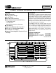
CS4360 24-Bit, 192 kHz 6-channel D/A Converter Features Description 24-bit Conversion 102 dB Dynamic Range -91 dB THD+N Low Clock Jitter Sensitivity Digital Volume Control with Soft Ramp The CS4360 is a complete 6-channel digital-to-analog system including digital interpolation, fourth-order deltasigma digital-to-analog conversion, digital de-emphasis, volume control, channel mixing and analog filtering.
CS4360 TABLE OF CONTENTS 1. PIN DESCRIPTION ................................................................................................................... 5 2. TYPICAL CONNECTION DIAGRAM ...................................................................................... 7 3. CHARACTERISTICS AND SPECIFICATIONS ........................................................................ 8 SPECIFIED OPERATING CONDITIONS .................................................................................
CS4360 4.5.1 Stand-alone Mode ............................................................................................... 24 4.5.2 Control Port Mode ............................................................................................... 24 4.6 Popguard® Transient Control .......................................................................................... 24 4.6.1 Power-up ............................................................................................................. 24 4.6.
CS4360 8. REFERENCES ........................................................................................................................ 36 9. PACKAGE DIMENSIONS ....................................................................................................... 37 LIST OF FIGURES Figure 1. Figure 2. Figure 3. Figure 4. Figure 5. Figure 6. Figure 7. Figure 8. Figure 9. Figure 10. Figure 11. Figure 12. Figure 13. Figure 14. Figure 15. Figure 16. Figure 17. Figure 18. Figure 19. Figure 20. Figure 21.
CS4360 1.
CS4360 Pin Name # Pin Description VLS 1 Serial Audio Interface Power (Input) - Positive power for the serial audio interface. SDIN1 SDIN2 SDIN3 2 3 4 Serial Audio Data Input (Input) - Input for two’s complement serial audio data. SCLK 5 Serial Clock (Input) - Serial clock for the serial audio interface. LRCK 6 Left Right Clock (Input) - Determines which channel, Left or Right, is currently active on the serial audio data line.
CS4360 2. TYPICAL CONNECTION DIAGRAM +3.3 V to +5 V * +3.3 V to VA * + 1 µF 22 VA 8 VD 6 Digital Audio Source 5 4 3 2 +1.8 V to +5 V * 1 MCLK AOUTB1 SDIN1 MUTEC1 SDIN3 AOUTA2 AOUTB2 VLS µ C/ Mode Configuration 12 13 15 +1.8 V to +5 V * 14 AOUTA1 10 kΩ C RL OPTIONAL 560 Ω 26 + 3.3 µF MUTE CIRCUIT 10 kΩ RST AOUTA3 RL C RL 28 560 Ω 24 + 3.3 µF AOUTA2 10 kΩ OPTIONAL 560 Ω 23 + 3.3 µF MUTE CIRCUIT 10 kΩ C 560 Ω 20 + 3.
CS4360 3. CHARACTERISTICS AND SPECIFICATIONS Typical performance characteristics are derived from measurements taken at TA = 25°C. Min/Max performance characteristics and specifications are guaranteed over the operating temperature and voltages. SPECIFIED OPERATING CONDITIONS GND = 0 V; all voltages with respect to GND. Parameters DC Power Supply Analog 3.3 V 5.0 V 2.5 V 3.3 V 5.0 V 1.8 V 2.5 V 3.3 V 5.0 V 1.8 V 2.5 V 3.3 V 5.
CS4360 ANALOG CHARACTERISTICS (CS4360-KZ/KZZ) Test conditions (unless otherwise specified): Input test signal is a 997 Hz sine wave at 0 dBFS; measurement bandwidth is 10 Hz to 20 kHz; test load RL = 10 kΩ, C L = 10 pF (see Figure 2). All supplies = VA = 5.0 V or 3.3 V. 5.
CS4360 ANALOG CHARACTERISTICS (CS4360-KZ/KZZ) (Continued) Parameters Symbol Min Typ Max Units - 102 - dB - 0.1 - dB - ±100 - ppm/°C Dynamic Performance for All Modes Interchannel Isolation (1 kHz) DC Accuracy Interchannel Gain Mismatch ICGM Gain Drift Analog Output Characteristics and Specifications Full Scale Output Voltage 0.60•VA 0.66•VA 0.
CS4360 ANALOG CHARACTERISTICS (CS4360-DZZ) Test conditions (unless otherwise specified): Input test signal is a 997 Hz sine wave at 0 dBFS; measurement bandwidth is 10 Hz to 20 kHz; test load R L = 10 kΩ, CL = 10 pF (see Figure 2). All supplies = VA = 5.0 V and 3.3 V. VA = 5.
CS4360 ANALOG CHARACTERISTICS (CS4360-DZZ) (Continued) Parameters Symbol Min Typ Max Units - 102 - dB - 0.1 - dB - ±100 - ppm/°C Dynamic Performance for All Modes Interchannel Isolation (1 kHz) DC Accuracy Interchannel Gain Mismatch ICGM Gain Drift Analog Output Characteristics and Specifications Full Scale Output Voltage 0.60•VA 0.66•VA 0.
CS4360 COMBINED INTERPOLATION & ON-CHIP ANALOG FILTER RESPONSE The filter characteristics and the X-axis of the response plots have been normalized to the sample rate (Fs) and can be referenced to the desired sample rate by multiplying the given characteristic by Fs. Parameter Min Typ Max Unit 0 0 - 0.4535 0.4998 Fs Fs -0.02 - +0.035 dB Single-Speed Mode (4 kHz to 50 kHz sample rates) Passband to -0.05 dB corner to -3 dB corner Frequency Response 10 Hz to 20 kHz StopBand 0.
CS4360 Figure 4. Single-speed Stopband Rejection Figure 5. Single-speed Transition Band Figure 6. Single-speed Transition Band (Detail) Figure 7. Single-speed Passband Ripple Figure 8. Double-speed Stopband Rejection 14 Figure 9.
CS4360 Figure 10. Double-speed Transition Band (Detail) DS517F2 Figure 11.
CS4360 SWITCHING SPECIFICATIONS - SERIAL AUDIO INTERFACE Inputs: Logic 0 = GND, Logic 1 = VLS. Parameters Symbol Min Max Units MCLK Frequency 1.024 51.
CS4360 SWITCHING SPECIFICATIONS - CONTROL PORT INTERFACE Inputs: Logic 0 = GND, Logic 1 = VLC Parameter Symbol Min Max Unit SCL Clock Frequency fscl - 100 kHz RST Rising Edge to Start tirs 500 - ns Bus Free Time Between Transmissions tbuf 4.7 - µs Start Condition Hold Time (prior to first clock pulse) thdst 4.0 - µs Clock Low time tlow 4.7 - µs Clock High Time thigh 4.0 - µs Setup Time for Repeated Start Condition tsust 4.
CS4360 SWITCHING SPECIFICATIONS - CONTROL PORT INTERFACE Parameter (Continued) Symbol Min Max Unit CCLK Clock Frequency fsclk - 6 MHz RST Rising Edge to CS Falling tsrs 500 - ns tspi 500 - ns CS High Time Between Transmissions tcsh 1.
CS4360 DC ELECTRICAL CHARACTERISTICS GND = 0 V; all voltages with respect to GND. Parameters Symbol Min Typ Max Units VA = 5.0 V VD = 5.0 V IA ID - 22 25 - mA mA VA = 3.3 V VD = 3.3 V IA ID - 21 14 - mA mA VLS = 5.0 V VLC = 5.0 V ILS ILC - 6 2 - µA µA VLS = 3.3 V VLC = 3.3 V ILS ILC - 2 1 - µA µA All Supplies = 5.0 V All Supplies = 3.3 V - 235 116 265 128 mW mW Power Supply Current All Supplies = 5.0 V All Supplies = 3.
CS4360 DIGITAL INTERFACE SPECIFICATIONS GND = 0 V; all voltages with respect to GND. Parameters Symbol Min Max Units 80% 80% - - VLS VLC 13% 13% VLS VLC - VLS VLC 13% 13% VLS VLC - VLS VLC 13% 13% VLS VLC - VLS VLC 13% 13% VLS VLC 1.
CS4360 4. APPLICATIONS 4.1 Sample Rate Range/Operational Mode Select 4.1.1 Stand-Alone Mode The device operates in one of four operational modes determined by the Mode pins in Stand-alone mode. Sample rates outside the specified range for each mode are not supported. M2 M1 0 0 1 1 0 1 0 1 Input Sample Rate (FS) 4 kHz - 50 kHz 32 kHz - 48 kHz 50 kHz - 100 kHz 100 kHz - 200 kHz MODE Single-Speed (without De-emphasis) Single-Speed (with De-emphasis) Double-Speed Quad-Speed Table 1.
CS4360 Sample Rate (kHz) 176.4 192 64x 11.2896 12.2880 96x 16.9344 18.4320 MCLK (MHz) 128x 22.5792 24.5760 192x 33.8688 36.8640 256x* 45.1584 49.1520 Table 5. Quad-speed Mode Standard Frequencies *Requires MCLKDIV bit = 1 in the Mode Control 2 register (address 0Ch) 4.3 Digital Interface Format The device will accept audio samples in 1 of 4 digital interface formats in Stand-alone mode, as illustrated in Table 6, and 1 of 6 formats in Control Port mode, as illustrated in Table 8. 4.3.
CS4360 4.3.2 Control Port Mode The desired format is selected via the DIF2, DIF1 and DIF0 bits in the Mode Control 2 register (see section 6.1.2). For an illustration of the required relationship between LRCK, SCLK and SDIN, see Figures 15-17. L e ft C ha n n el LRC K R ig ht C h a n n el S CLK S D IN MSB -1 -2 -3 -4 -5 +5 +4 +3 +2 +1 M SB LS B +5 +4 +3 +2 +1 -1 -2 -3 -4 LS B Figure 15.
CS4360 4.4.1 Stand-Alone Mode The operational mode pins, M2 and M1, selects the 44.1 kHz de-emphasis filter. Please see section 4.1 for the desired de-emphasis control. 4.4.2 Control Port Mode The Mode Control bits selects either the 32, 44.1, or 48 kHz de-emphasis filter. Please see section 6.1.3 for the desired de-emphasis control. 4.5 4.5.
CS4360 4.6.3 Discharge Time To prevent an audio transient at the next power-on, the DC-blocking capacitors must fully discharge before turning on the power or exiting the power-down state. If full discharge does not occur, a transient will occur when the audio outputs are initially clamped to GND. The time that the device must remain in the power-down state is related to the value of the DC-blocking capacitance and the output load. For example, with a 3.
CS4360 4.9.1 Memory Address Pointer (MAP) The MAP byte precedes the control port register byte during a write operation and is not available again until after a start condition is initiated. During a read operation the byte transmitted after the ACK will contain the data of the register pointed to by the MAP (see sections 4.9.1a and 4.9.3 for write/read details). 7 INCR 0 4.9.
CS4360 SDA 0 01 00 0 AD0 W ACK M AP 1 -8 ACK D A TA 1-8 ACK SCL S top S ta rt Figure 19. I²C Write 4.9.2b I²C Read To read from the device, follow the procedure below while adhering to the control port Switching Specifications. During this operation it is first necessary to write to the device, specifying the appropriate register through the MAP. 1) After writing to the MAP (see section 4.9.1), initiate a repeated START condition to the I²C bus followed by the address byte.
CS4360 4.9.3a SPI Write To write to the device, follow the procedure below while adhering to the control port Switching Specifications in section 3. 1) Bring CS low. 2) The address byte on the CDIN pin must then be 00100000. 3) Write to the memory address pointer, MAP. This byte points to the register to be written. 4) Write the desired data to the register pointed to by the MAP. 5) If the INCR bit (see section 4.9.
CS4360 5.
CS4360 6. REGISTER DESCRIPTIONS Note: All registers are read/write in I²C mode and write only in SPI, unless otherwise stated. 6.1 MODE CONTROL 1 (ADDRESS 01H) 7 AMUTE 1 6.1.1 6 DIF2 0 5 DIF1 0 AUTO-MUTE (AMUTE) 4 DIF0 0 3 DEM1 0 2 DEM0 0 1 FM1 0 0 FM0 0 BIT 7 Default = 1 0 - Disabled 1 - Enabled Function: The Digital-to-Analog converter output will mute following the reception of 8192 consecutive audio samples of static 0 or 1. A single sample of non-static data will release the mute.
CS4360 6.1.3 DE-EMPHASIS CONTROL (DEM) BIT 2-3 Default = 00 00 - Disabled 01 - 44.1 kHz 10 - 48 kHz 11 - 32 kHz Function: Selects the appropriate digital filter to maintain the standard 15 µs/50 µs digital de-emphasis filter response at 32-, 44.1- or 48-kHz sample rates. (See Figure 18.) Note: 6.1.4 De-emphasis is only available in Single-speed Mode.
CS4360 6.3.1 ATAPI CHANNEL MIXING AND MUTING (ATAPI) BIT 0-3 Default = 1001 - AOUTAx = L, AOUTBx = R (Stereo) Function: The CS4360 implements the channel mixing functions of the ATAPI CD-ROM specification. Refer to Table 9 and Figure 22 for additional information. Note: All mixing functions occur prior to the digital volume control. Mixing only occurs in channel pairs.
CS4360 6.4 VOLUME CONTROL (ADDRESSES 06H - 0BH) 7 xx_MUTE 0 6.4.1 6 xx_VOL6 0 MUTE (MUTE) 5 xx_VOL5 0 4 xx_VOL4 0 3 xx_VOL3 0 2 xx_VOL2 0 1 xx_VOL1 0 0 xx_VOL0 0 BIT 7 Default = 0 0 - Disabled 1 - Enabled Function: The Digital-to-Analog converter output will mute when enabled. The quiescent voltage on the output will be retained. The muting function is affected, similar to attenuation changes, by the Soft and Zero Cross bits.
CS4360 Zero Cross Zero Cross Enable dictates that signal level changes, either by attenuation changes or muting, will occur on a signal zero crossing to minimize audible artifacts. The requested level change will occur after a timeout period between 512 and 1024 sample periods (10.7 ms to 21.3 ms at 48 kHz sample rate) if the signal does not encounter a zero crossing. The zero cross function is independently monitored and implemented for each channel.
CS4360 6.5.5 FREEZE CONTROLS (FREEZE) BIT 2 Default = 0 0 - Disabled 1 - Enabled Function: This function allows modifications to be made to the registers without the changes taking effect until the FREEZE is disabled. To have multiple changes in the control port registers take effect simultaneously, enable the FREEZE bit, make all register changes, then disable the FREEZE bit. 6.5.
CS4360 7. PARAMETER DEFINITIONS Total Harmonic Distortion + Noise (THD+N) The ratio of the RMS value of the signal to the RMS sum of all other spectral components over the specified bandwidth (typically 10 Hz to 20 kHz), including distortion components. Expressed in decibels. Dynamic Range The ratio of the full-scale RMS value of the signal to the RMS sum of all other spectral components over the specified bandwidth.
CS4360 9. PACKAGE DIMENSIONS 28L TSSOP (4.4 mm BODY) PACKAGE DRAWING N D E11 A2 E A ∝ e b2 SIDE VIEW A1 L END VIEW SEATING PLANE 1 2 3 TOP VIEW INCHES DIM A A1 A2 b D E E1 e L ∝ MIN -0.002 0.03150 0.00748 0.378 BSC 0.248 0.169 -0.020 0° NOM -0.004 0.035 0.0096 0.382 BSC 0.2519 0.1732 0.026 BSC 0.024 4° NOTE MILLIMETERS MAX 0.47 0.006 0.04 0.012 0.386 BSC 0.256 0.177 -0.029 8° MIN -0.05 0.80 0.19 9.60 BSC 6.30 4.30 -0.50 0° NOM -0.10 0.90 0.245 9.70 BSC 6.40 4.40 0.65 BSC 0.60 4° MAX 1.