
User guide

6 DS803F3
CS4353
2. CHARACTERISTICS AND SPECIFICATIONS
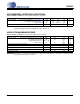
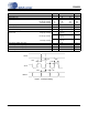
RECOMMENDED OPERATING CONDITIONS
AGND = DNGD = CPGND = 0 V; all voltages with respect to ground.
Note: 1. VCP and VA must be supplied with the same nominal voltage. Additional current draw will occur if the sup-
ply voltages applied to VCP and VA differ by more than 0.5 V.
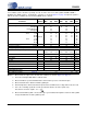
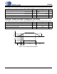
ABSOLUTE MAXIMUM RATINGS
AGND = DNGD = CPGND = 0 V; all voltages with respect to ground.
WARNING: Operation at or beyond these limits may result in permanent damage to the device. Normal operation
is not guaranteed at these extremes.
Parameters Symbol Min Typ Max Units
DC Power Supply Charge Pump and Digital Core power (Note 1)
Low Voltage Analog power (Note 1)
Interface power
VCP
VA
VL
3.13
3.13
0.85
3.3
3.3
0.9 to 3.3
3.47
3.47
3.47
V
V
V
Ambient Operating Temperature (Power Applied) T
A
-40 - +85 °C
Parameters Symbol Min Max Units
DC Power Supply Charge Pump and Digital Core Logic Power
Low Voltage Analog Power
Supply Voltage Difference
Interface Power
VCP
VA
|VCP - VA|
VL
-0.3
-0.3
-
-0.3
3.63
3.63
0.5
3.63
V
V
V
V
Input Current, Any Pin Except Supplies I
in
-±10mA
Digital Input Voltage Digital Interface V
IN-L
-0.3 V
L
+ 0.4 V
Analog Input Voltage AOUT_REF V
IN-A
-0.3 0.5 V
Ambient Operating Temperature (Power Applied) T
A
-55 +125 °C
Storage Temperature T
stg
-65 +150 °C