
User guide

24 DS803F3
CS4353
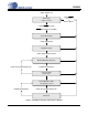
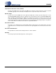
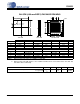
7. PACKAGE DIMENSIONS
Notes: 1. Dimensioning and tolerance per ASME Y 14.5M-1994.
2. Dimensioning lead width applies to the metallized terminal and is measured between 0.15 mm and
0.30 mm from the terminal tip.
INCHES MILLIMETERS
NOTE
DIM MIN NOM MAX MIN NOM MAX
A - - 0.03937 - - 1.00 1
A1 0.00000 - 0.00197 0.00 - 0.05 1
b 0.00787 0.00984 0.01181 0.20 0.25 0.30 1, 2
e 0.01772 0.01969 0.02165 0.45 0.50 0.55 1
D 0.15748 BSC 4.00 BSC 1
D2 0.10433 0.10630 0.10827 2.65 2.70 2.75 1
E 0.15748 BSC 4.00 BSC 1
E2 0.10433 0.10630 0.10827 2.65 2.70 2.75 1
L 0.01181 0.01575 0.01969 0.30 0.40 0.50 1
Controlling Dimension is Millimeters
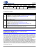
Parameter Symbol Min Typ Max Units
Junction to Ambient Thermal Impedance 2 Layer Board
4 Layer Board
JA
JA
-
-
68
28
-
-
°C/Watt
°C/Watt
PIN #1
CORNER
L
A
A1
e
b
D2
E2
D
1.00 REF
1.00 REF
PIN #1 IDENTIFIER
LASER MARKING
E
TOP VIEW SIDE VIEW BOTTOM VIEW
24L QFN (4.00 mm BODY) PACKAGE DRAWING