
Manual

DS566F1 27
CS4351
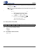
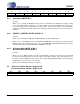
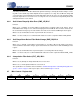
6.4 Mute Control - Register 04h
6.4.1 Auto-Mute (AMUTE) Bit 7
Function:
When set to 1 (default), the Digital-to-Analog converter output will mute following the reception of 8192
consecutive audio samples of static 0 or -1. A single sample of non-static data will release the mute. De-
tection and muting is done independently for each channel. The quiescent voltage on the output will be
retained and the Mute Control pin will go active during the mute period. When set to 0, this function is
disabled
6.4.2 AMUTEC = BMUTEC (MUTEC A=B) Bit 5
Function:
When set to 0 (default), the AMUTEC and BMUTEC pins operate independently.
When set to 1, the individual controls for AMUTEC and BMUTEC are internally connected through an
AND gate prior to the output pins. Therefore, the external AMUTEC and BMUTEC pins will go active only
when the requirements for both AMUTEC and BMUTEC are valid.
6.4.3 A Channel Mute (MUTE_A) Bit 4
B Channel Mute (MUTE_B) Bit 3
Function:
When set to 1, the Digital-to-Analog converter output will mute. The quiescent voltage on the output will
be retained. The muting function is effected, similar to attenuation changes, by the Soft and Zero Cross
bits in the Volume and Mixing Control register. The corresponding MUTEC pin will go active following any
ramping due to the soft and zero cross function.
When set to 0 (default), this function is disabled.
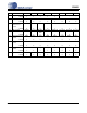
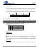
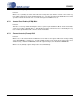
6.5 Channel A Volume Control - Register 05h
Channel B Volume Control - Register 06h
76543210
AMUTE Reserved MUTEC A=B MUTE_A MUTE_B Reserved Reserved Reserved
10000000
76543210
VOL7 VOL6 VOL5 VOL4 VOL3 VOL2 VOL1 VOL0
00000000