
Manual

22 DS566F1
CS4351
4. Write the desired data to the register pointed to by the MAP.
5. If the INCR bit (see Section 4.9.1) is set to 1, repeat the previous step until all the desired registers
are written, then bring CS
high.
6. If the INCR bit is set to 0 and further SPI writes to other registers are desired, it is necessary to bring
CS
high, and follow the procedure detailed from step 1. If no further writes to other registers are de-
sired, bring CS
high.
)
4.10 Memory Address Pointer (MAP)
4.10.1 INCR (AUTO MAP INCREMENT ENABLE)
Default = ‘0’
0 - Disabled
1 - Enabled
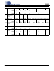
4.10.2 MAP (MEMORY ADDRESS POINTER)
Default = ‘0000’
76543210
INCR Reserved Reserved Reserved MAP3 MAP2 MAP1 MAP0
00000000
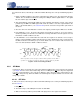
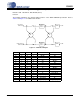
MAP
MSB
LSB
DATA
byte 1
byte n
R/W
MAP = Memory Address Pointer
ADDRESS
CHIP
CDIN
CCLK
CS
1001100
Figure 10. Control Port Timing, SPI mode