
Manual

16 DS566F1
CS4351
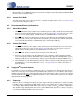
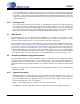
4.3 Digital Interface Format
The device will accept audio samples in 1 of 4 digital interface formats in Stand-Alone mode, as illustrated
in Table 6, and 1 of 6 formats in Control Port mode, as illustrated in Table 7.
4.3.1 Stand-Alone Mode
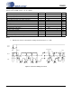
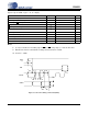
The desired format is selected via the DIF1 and DIF0 pins. For an illustration of the required relationship
between the LRCK, SCLK and SDIN, see Figures 5 through 7. For all formats, SDIN is valid on the rising
edge of SCLK. Also, SCLK must have at least 32 cycles per LRCK period in format 2, and 48 cycles per
LRCK period in format 3.
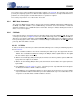
4.3.2 Control Port Mode
The desired format is selected via the DIF2, DIF1 and DIF0 bits in the Mode Control 2 register (see section
Section 6.2.1). For an illustration of the required relationship between LRCK, SCLK and SDIN, see
Figures 5 through 7. For all formats, SDIN is valid on the rising edge of SCLK. Also, SCLK must have at
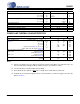
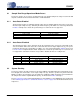
Sample Rate
(kHz)
MCLK (MHz)
256x 384x 512x 768x 1024x 1152x
32 8.1920 12.2880 16.3840 24.5760 32.7680 36.8640
44.1 11.2896 16.9344 22.5792 33.8688 45.1584
48 12.2880 18.4320 24.5760 36.8640 49.1520
Table 3. Single-Speed Mode Standard Frequencies
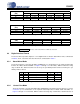
Sample Rate
(kHz)
MCLK (MHz)
128x 192x 256x 384x 512x
64 8.1920 12.2880 16.3840 24.5760 32.7680
88.2 11.2896 16.9344 22.5792 33.8688 45.1584
96 12.2880 18.4320 24.5760 36.8640 49.1520
Table 4. Double-Speed Mode Standard Frequencies
Sample Rate
(kHz)
MCLK (MHz)
64x 96x 128x 192x 256x
176.4 11.2896 16.9344 22.5792 33.8688 45.1584
192
12.2880 18.4320 24.5760 36.8640 49.1520
Table 5. Quad-Speed Mode Standard Frequencies
= Denotes clock modes which are NOT auto detected
DIF0 DIF1 DESCRIPTION FORMAT FIGURE
00
I
2
S, up to 24-bit Data
0 6
01
Left Justified, up to 24-bit Data
1 5
10
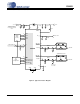
Right Justified, 24-bit Data
2 7
11
Right Justified, 16-bit Data
3 7
Table 6. Digital Interface Format - Stand-Alone Mode