
Manual


28 DS691F2
CS4350
8 REGISTER DESCRIPTION
Note: All register access is Read/Write unless specified otherwise
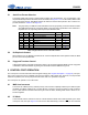
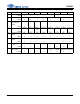
8.1 Device and Revision ID - Register 01h
Function:
This register is Read-Only. It is decoded as follows:
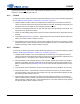
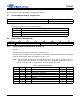
8.2 Mode Control - Register 02h
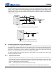
8.2.1 Digital Interface Format (DIF[2:0]) Bits 6-4
Function:
These bits select the interface format for the serial audio input.
The required relationship between the Left/Right clock, serial clock and serial data is defined by the Digital
Interface Format and the options are detailed in Figures 11-13.
Note: The group delay for TDM slot 0 channel B differs from the group delay of all other interface for-
mats and TDM slots/channels by one sample. Refer to the group delay specification in the com-
bined interpolation and on-chip analog filter response specifications table.
76543210
Device4 Device3 Device2 Device1 Device0 Rev2 Rev1 Rev0
1111- - - -
Rev Register 01h contents
A 1111,0000
B 1111,0001
C2 1111,1111
76543210
Reserved DIF2 DIF1 DIF0 DEM1 DEM0 FM1 FM0
00000000
Table 13. Digital Interface Formats
DIF2 DIF1 DIF0 Description Format Figure
000
Left-Justified, up to 24-bit data 0 (Default)
11
001
I²S, up to 24-bit data
1 12
010
Right-Justified, 16-bit data
2 13
011
Right-Justified, 24-bit data
3 13
100
TDM slot 0
4 15
101
TDM slot 1
5 15
110
TDM slot 2
6 15
111
TDM slot 3
7 15