
Manual

20 DS691F2
CS4350
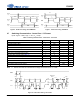
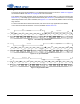
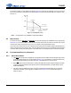
4.4 De-Emphasis
The device includes on-chip digital de-emphasis. Figure 16 shows the de-emphasis curve for Fs equal to
44.1 kHz. The frequency response of the de-emphasis curve will scale proportionally with changes in sam-
ple rate, Fs.
Note: De-emphasis is only available in Single-Speed Mode.
4.5 Mute Control
The mute control pins (AMUTEC and BMUTEC) go active during power-up initialization, reset, muting (see
Section 8.4.3), and loss of LRCK. These pins are intended to be used as control for external mute circuits
to prevent the clicks and pops that can occur in any single-ended single-supply system.
Use of the mute control function is not mandatory but recommended for designs requiring the absolute min-
imum in extraneous clicks and pops. Also, use of the Mute Control function can enable the system designer
to achieve idle-channel noise and signal-to-noise ratios which are only limited by the external mute circuit.
4.6 Recommended Power-Up Sequence
4.6.1 Stand-Alone Mode
1. Hold RST low until the power supplies and configuration pins are stable and the left/right clock is fixed
to the appropriate frequencies, as discussed in Section 4.2. In this state, the control port registers are
reset to their default settings, VQ will remain low, and VBIAS will be connected to VA.
2. Bring RST
high. The device will remain in a low power state with VQ low for approximately 192 LRCK
cycles in Single-Speed Mode (384 LRCK cycles in Double-Speed Mode, and 768 LRCK cycles in
Quad-Speed Mode).
3. The device will then initiate the power up sequence which lasts approximately 130 ms when the
Popguard is disabled. If the Popguard is enabled, see Section 4.7 for a complete description of
power-up timing.
Gain
dB
-10dB
0dB
Frequency
T2 = 15 µs
T1=50 µs
F1 F2
3.183 kHz 10.61 kHz
Figure 16. De-Emphasis Curve