
Manual

CS4341A
32 DS582F2
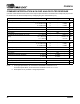
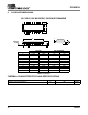
DC ELECTRICAL CHARACTERISTICS (AGND = 0 V; all voltages with respect to AGND.)
DIGITAL INPUT CHARACTERISTICS (AGND = 0 V; all voltages with respect to AGND.)
DIGITAL INTERFACE SPECIFICATIONS (GND = 0 V; all voltages with respect to GND.)
12. Normal operation is defined as RST
= HI with a 997 Hz, 0dBFS input sampled at the highest F
s
for each
speed mode, and open outputs, unless otherwise specified.
13. Power Down Mode is defined as RST
= LO with all clocks and data lines held static.
14. Valid with the recommended capacitor values on FILT+ and VQ as shown in Figure 1. Increasing the
capacitance will also increase the PSRR.
Parameters Symbol Min Typ Max Units
Normal Operation
(Note 12)
Power Supply Current VA = 5.0 V
VA = 3.3 V
I
A
-
-
18
15
25
20
mA
mA
Power Dissipation VA = 5.0 V
VA = 3.3 V
-
-
90
50
125
100
mW
mW
Power-down Mode
(Note 13)
Power Supply Current VA = 5.0 V
VA = 3.3 V
I
A
-
-
60
35
-
-
µA
µA
Power Dissipation VA = 5.0 V
VA = 3.3 V
-
-
0.3
0.1
-
-
mW
mW
All Modes of Operation
Power Supply Rejection Ratio
(Note 14) 1 kHz
60 Hz
PSRR -
-
60
40
-
-
dB
dB
V
Q
Nominal Voltage
Output Impedance
Maximum allowable DC current source/sink
-
-
-
0.5•VA
250
0.01
-
-
-
V
kΩ
mA
Filt+ Nominal Voltage
Output Impedance
Maximum allowable DC current source/sink
-
-
-
VA
250
0.01
-
-
-
V
kΩ
mA
MUTEC Low-Level Output Voltage - 0 - V
MUTEC High-Level Output Voltage - VA - V
Maximum MUTEC Drive Current - 3 - mA
Parameters Symbol Min Typ Max Units
Input Leakage Current I
in
--±10µA
Input Capacitance - 8 - pF
Parameters Symbol Min Max Units
Interface Voltage Supply = 3.3 V or 5.0 V
High-Level Input Voltage V
IH
2.0 - V
Low-Level Input Voltage V
IL
-0.8 V