
Manual

CS4341A
30 DS582F2
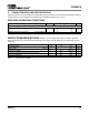
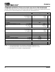
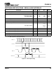
SWITCHING SPECIFICATIONS - CONTROL PORT INTERFACE
(Inputs: Logic 0 = AGND, Logic 1 = VA)
Notes: 7. Data must be held for sufficient time to bridge the transition time, t
fc
, of SCL.
8. See “Rise Time for Control Port Clock” on page 11. for a recommended circuit to meet rise time
specification.
Parameter Symbol Min Max Unit
I
2
C Mode
SCL Clock Frequency f
scl
- 100 kHz
RST
Rising Edge to Start
t
irs
500 - ns
Bus Free Time Between Transmissions t
buf
4.7 - µs
Start Condition Hold Time (prior to first clock pulse) t
hdst
4.0 - µs
Clock Low time t
low
4.7 - µs
Clock High Time t
high
4.0 - µs
Setup Time for Repeated Start Condition t
sust
4.7 - µs
SDA Hold Time from SCL Falling
(Note 7) t
hdd
0-µs
SDA Setup time to SCL Rising t
sud
250 - ns
Rise Time of SCL
(Note 8) t
rc
-25ns
Fall Time SCL t
fc
-25ns
Rise Time of SDA t
rd
-1µs
Fall Time SDA t
fd
-300ns
Setup Time for Stop Condition t
susp
4.7 - µs
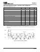
t
buf
t
hdst
t
hdst
t
low
t
r
t
f
t
hdd
t
high
t
sud
t
sust
t
susp
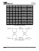
Stop S ta rt
Start
Stop
Repeated
SDA
SCL
t
irs
RST
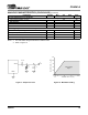
Figure 19. Control Port Timing - I
2
C Mode