
User guide

CS4341
18 DS298F5
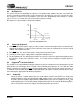
4.2.2 External Serial Clock Mode
The device will enter the External Serial Clock Mode whenever 16 low to high transitions are de-
tected on the SCLK pin during any phase of the LRCK period. The device will revert to Internal
Serial Clock Mode if no low to high transitions are detected on the SCLK pin for 2 consecutive pe-
riods of LRCK.
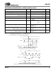
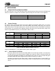
4.3 Digital Interface Format
The device will accept audio samples in several digital interface formats. The desired format is selected
via the DIF0, DIF1 and DIF2 bits in the Mode Control register (see section 6.2.2). For an illustration of the
required relationship between LRCK, SCLK and SDATA, see Figures 17 through 19.
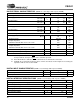
Input
Digital Interface Format Selection Internal
MCLK/LRCK
Ratio
I
2
S up to 16 or
24 Bits
Left Justified 24
Bits
Right Justified
18, 20 or 24 Bits
Right Justified
16 Bits
SCLK/LRCK
Ratio
512, 256, 128
(Format 1) - - X 32
384, 192
XX X X48
512, 256, 128
(Format 0) X X - 64
Table 4. Internal SCLK/LRCK Ratio
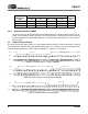
LRCK
SCLK
Left Channel
Right Channel
SDATA +3 +2 +1+5 +4
MSB
-1 -2 -3 -4 -5
+3 +2 +1+5 +4
-1 -2 -3 -4
LSB
MSB LSB
Figure 17. CS4341 Formats 0-1 - I²S up to 24-Bit Data
LRCK
SCLK
Left Channel
Right Channel
SDATA +3 +2 +1+5 +4
MSB
-1 -2 -3 -4 -5
+3 +2 +1+5 +4
-1 -2 -3 -4
LSB
MSB
LSB
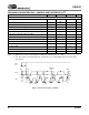
Figure 18. CS4341 Format 2 - Left Justified up to 24-Bit Data
LRCK
SCLK
Left Channel
SDATA
+6 +5 +4 +3 +2+1+7
-1 -2 -3 -4
-5
LSB
Right Channel
MSB LSB
+6 +5 +4 +3 +2+1+7
-1 -2 -3 -4
-5
MSB LSB
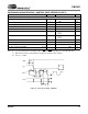
Figure 19. CS4341 Formats 3-6 - Right Justified