
User guide

CS4341
DS298F5 17
4. APPLICATIONS
4.1 Sample Rate Range/Operational Mode
The device operates in one of two operational modes determined by the Master Clock to Left/Right Clock
ratio (see section 4.2). Sample rates outside the specified range for each mode are not supported.
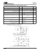
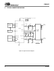
4.2 System Clocking
The device requires external generation of the master (MCLK) and left/right (LRCK) clocks. The device
also requires external generation of the serial clock (SCLK) if the internal serial clock is not used. The
LRCK, defined also as the input sample rate Fs, must be synchronously derived from MCLK according to
specified ratios. The specified ratios of MCLK to LRCK, along with several standard audio sample rates
and the required MCLK frequency, are illustrated in Tables 2 and 3.
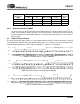
*Requires MCLKDIV bit = 1 in the MCLK Control (address 00h) register.
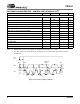
4.2.1 Internal Serial Clock Mode
The device will enter the Internal Serial Clock Mode if no low to high transitions are detected on
the SCLK pin for 2 consecutive periods of LRCK. In this mode, the SCLK is internally derived and
synchronous with MCLK and LRCK. The SCLK/LRCK ratio is either 32, 48, or 64 depending upon
the MCLK/LRCK ratio and the Digital Interface Format selection (see Table 4).
Operation in the Internal Serial Clock mode is identical to operation with an external SCLK syn-
chronized with LRCK; however, External SCLK mode is recommended for system clocking appli-
cations.
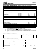
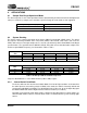
Input Sample Rate (Fs) MODE
4 kHz - 50 kHz Single-Speed Mode
50 kHz - 100 kHz Double-Speed Mode
Table 1. CS4341 Speed Modes
Sample Rate
(kHz)
MCLK (MHz)
256x 384x 512x 768x* 1024x*
32 8.1920 12.2880 16.3840 24.5760 32.768
44.1 11.2896 16.9344 22.5792 33.8688 45.1584
48 12.2880 18.4320 24.5760 36.8640 49.1520
Table 2. Single-Speed Mode Standard Frequencies
Sample Rate
(kHz)
MCLK (MHz)
128x 192x 256x* 384x*
64 8.1920 12.2880 16.3840 24.5760
88.2 11.2896 16.9344 22.5792 33.8688
96 12.2880 18.4320 24.5760 36.8640
Table 3. Double-Speed Mode Standard Frequencies