
Manual


CS4340
DS297F3 17
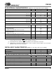
The internal serial clock is utilized when additional de-emphasis control is required. Operation in the Internal
Serial Clock mode is identical to operation with an external SCLK synchronized with LRCK; however, External
SCLK mode is recommended for system clocking applications.
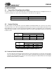
4.2.2 External Serial Clock Mode
The device will enter the External Serial Clock Mode whenever 16 low to high transitions are detected on the
SCLK pin during any phase of the LRCK period. The device will revert to Internal Serial Clock Mode if no low
to high transitions are detected on the SCLK pin for 2 consecutive periods of LRCK.
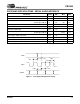
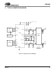
4.3 Digital Interface Format
The device will accept audio samples in several digital interface formats as illustrated in Table 5. The desired format
is selected via the DIF1 and DIF0 pins. For an illustration of the required relationship between LRCK, SCLK and
SDIN, see Figures 15 through 18.
Input
Digital Interface Format Selection Internal
MCLK/LRCK
Ratio
I
2
S up to 24
Bits
Left Justified 24
Bits
Right Justified
24 Bits
Right Justified
16 Bits
SCLK/LRCK
Ratio
512, 256, 128
X- - X32
384, 192
XX X X48
512, 256, 128
-XX -64
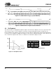
Table 4. Internal SCLK/LRCK Ratio
DIF1 DIF0 DESCRIPTION FORMAT FIGURE
00
I
2
S, up to 24-bit data
015
01
Left Justified, up to 24-bit data
116
10
Right Justified, 24-bit Data
217
11
Right Justified, 16-bit Data
318
Table 5. Digital Interface Format - DIF1 and DIF0
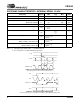
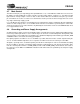
LRCK
SCLK
Left Channel
Right Channel
SDIN +3 +2 +1+5 +4
MSB
-1 -2 -3 -4 -5
+3 +2 +1+5 +4
-1 -2 -3 -4
LSB
MSB LSB
Figure 15. CS4340 Format 0 - I
2
S up to 24-Bit Data
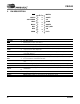
LRCK
SCLK
Left Channel
Right Channel
SDIN +3 +2 +1+5 +4
MSB
-1 -2 -3 -4 -5
+3 +2 +1+5 +4
-1 -2 -3 -4
LSB
MSB
LSB
Figure 16. CS4340 Format 1 - Left Justified up to 24-Bit Data