
User guide

3
CS4334/5/8/9
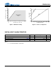
Figure 18. Passband Ripple...................................................................................................................... 18
Figure 19. Stopband Rejection.................................................................................................................. 19
Figure 20. Transition Band........................................................................................................................ 19
Figure 21. Transition Band........................................................................................................................ 19
Figure 22. Passband Ripple...................................................................................................................... 19
Figure 23. 0 dBFS FFT (BRM) .................................................................................................................. 20
Figure 24. -60 dBFS FFT (BRM).............................................................................................................. 20
Figure 25. Idle Channel Noise FFT (BRM)................................................................................................ 20
Figure 26. Twin Tone IMD FFT (BRM)...................................................................................................... 20
Figure 27. THD+N vs. Amplitude (BRM)................................................................................................... 20
Figure 28. THD+N vs. Frequency (BRM).................................................................................................. 20
Figure 29. 0 dBFS FFT (HRM).................................................................................................................. 21
Figure 30. -60 dBFS FFT (HRM).............................................................................................................. 21
Figure 31. Idle Channel Noise FFT (HRM) ............................................................................................... 21
Figure 32. Twin Tone IMD FFT (HRM) ..................................................................................................... 21
Figure 33. THD+N vs. Amplitude (HRM)................................................................................................... 21
Figure 34. THD+N vs. Frequency (HRM).................................................................................................. 21
LIST OF TABLES
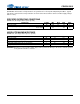
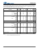
Table 1. Common Clock Frequencies ...................................................................................................... 13
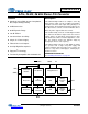
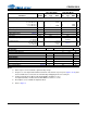
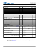
PIN DESCRIPTIONS
No. Pin Name I/O Pin Function and Description
1SDATAI
Serial Audio Data Input - Two’s complement MSB-first serial data is input on this pin. The data is
clocked into the CS4334/5/8/9 via internal or external SCLK, and the channel is determined by
LRCK.
2DEM/SCLK I
De-Emphasis/External Serial Clock Input - Used for de-emphasis filter control or external serial
clock input.
3 LRCK I
Left/Right Clock - Determines which channel is currently being input on the Audio Serial Data
Input pin, SDATA.
4MCLKI
Master Clock - Frequency must be 256x, 384x, or 512x the input sample rate in BRM and either
128x or 192x the input sample rate in HRM.
5AOUTROAnalog Right Channel Output - Typically 3.5 Vp-p for a full-scale input signal.
6AGNDIAnalog Ground - Analog ground reference is 0V.
7VAIAnalog Power - Analog power supply is nominally +5 V.
8AOUTLOAnalog Left Channel Output - Typically 3.5 Vp-p for a full-scale input signal.
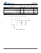
SERIAL DATA INPUT SDATA AOUTL ANALOG LEFT CHANNEL OUTPUT
DE-EMPHASIS / SCLK DEM/SCLK VA ANALOG POWER
LEFT / RIGHT CLOCK LRCK AGND ANALOG GROUND
MASTER CLOCK MCLK AOUTR ANALOG RIGHT CHANNEL OUTPUT
72
63
54
81