
User guide

10
CS4334/5/8/9
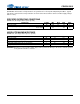
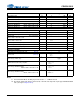
SWITCHING CHARACTERISTICS
Notes:
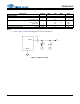
9. In Internal SCLK Mode, the Duty Cycle must be 50% 1/2 MCLK Period.
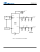
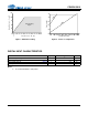
10. The SCLK / LRCK ratio may be either 32, 48, or 64. This ratio depends on part type and MCLK/LRCK
ratio. (See figures Figures 10-13)
Parameters Symbol Min Typ Max Units
Input Sample Rate Fs 2 - 100 kHz
MCLK Pulse Width High MCLK/LRCK = 512 10 - 1000 ns
MCLK Pulse Width Low MCLK/LRCK = 512 10 - 1000 ns
MCLK Pulse Width High MCLK / LRCK = 384 or 192 21 - 1000 ns
MCLK Pulse Width Low MCLK / LRCK = 384 or 192 21 - 1000 ns
MCLK Pulse Width High MCLK / LRCK = 256 or 128 31 - 1000 ns
MCLK Pulse Width Low MCLK / LRCK = 256 or 128 31 - 1000 ns
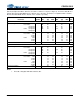
External SCLK Mode
LRCK Duty Cycle (External SCLK only) 40 50 60 %
SCLK Pulse Width Low t
sclkl
20 - - ns
SCLK Pulse Width High t
sclkh
20 - - ns
SCLK Period Base-Rate Mode
MCLK / LRCK = 512, 256 or 384
t
sclkw
--ns
SCLK Period High-Rate Mode
MCLK / LRCK = 128 or 192
t
sclkw
--ns
SCLK rising to LRCK edge delay t
slrd
20 - - ns
SCLK rising to LRCK edge setup time t
slrs
20 - - ns
SDATA valid to SCLK rising setup time t
sdlrs
20 - - ns
SCLK rising to SDATA hold time t
sdh
20 - - ns
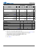
Internal SCLK Mode
LRCK Duty Cycle (Internal SCLK only) (Note 9) -50-%
SCLK Period (Note 10)
t
sclkw
--ns
SCLK rising to LRCK edge
t
sclkr
--s
SDATA valid to SCLK rising setup time
t
sdlrs
--ns
SCLK rising to SDATA hold time
MCLK / LRCK = 512, 256 or 128
t
sdh
--ns
SCLK rising to SDATA hold time
MCLK / LRCK = 384 or 192
t
sdh
--ns
1
128Fs
----------------------
1
64Fs
-------------------
1
SCLK
-----------------
tsclkw
2
------------------
1
512Fs
----------------------10+
1
512Fs
----------------------15+
1
384Fs
----------------------15+