
User guide

6
CS42L73
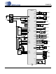
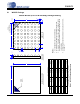
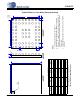
2.2 FBGA Package
65 Ball FBGA (5x5mm Body) Package Drawing
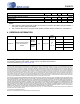
MILLIMETERS
Dim MIN NOM MAX
A 0.740.871.00
A1 0.16 0.21 0.26
A2 0.58 0.66 0.74
M - 4.00 -
N - 4.00 -
b 0.270.300.37
c - 0.50 -
d - 0.50 -
e - 0.50 -
X 4.905.005.10
Y 4.905.005.10
Controlling Dimension is Millimeters.
Table 2. FBGA Package Dimensions
Notes:
1. Controlling dimensions are in millimeters.
2. Dimensioning and tolerances per ASME Y 14.5M-1994.
3. Dimension “b” applies to the solder sphere diameter and is
measured at the midpoint between the package body and the
seating plane.
4. Unless otherwise specified, tolerances are: Linear ±0.05 mm,
Angular ±1°.
e
e
A2
Ball A1
Location
Indicator
X
Y
BUMP SIDESIDE VIEW
A1
b
N
M
d
c
TOP SIDE
Ball A1
Location
Indicator
Ball A1
A