
Instruction Manual


DS882F1 91
CS42L73
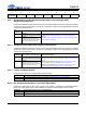
6.14 VSP Control (Address 10h)
6.14.1 Tristate VSP Interface
Determines the state of the VSP drivers.
Note: Slave/Master Mode is determined by the register control bit VSP Master/Slave Mode described
on page 92.
6.14.2 VSP Digital Interface Format
Configures the XSP digital interface format.
6.14.3 VSP PCM Interface Mode
Applicable only if VSPDIF = 1b (PCM Format). Configures the VSP PCM interface mode.
6.14.4 VSP PCM Format Bit Order
Applicable only if VSPDIF = 1b (PCM Format). Configures the order in which bits are transmitted on VSP_
SDOUT and received on VSP_SDIN.
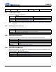
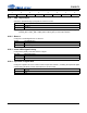
76543210
3ST_VSP VSPDIF V_PCM_MODE1 V_PCM_MODE0 V_PCM_BIT_
ORDER
V_SDIN_LOC V_SCK=MCK1 V_SCK=MCK0
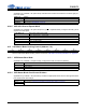
3ST_VSP
VSP State
Slave Mode Master Mode
0 Serial port clocks are inputs and SDOUT is output Serial port clocks and SDOUT are outputs
1 Serial port clocks are inputs and SDOUT is HI-Z Serial port clocks and SDOUT are HI-Z
Application: Refer to section “High-impedance Mode” on page 52.
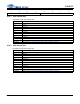
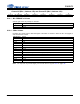
VSPDIF VSP Interface Format
0 I²S
1 PCM (must also set V_PCM_MODE[1:0] and V_PCM_BIT_ORDER)
Application: Refer to section “Formats” on page 54.
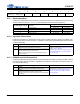
V_PCM_MODE[1:0] VSP PCM Interface Mode
00 Mode 0
01 Mode 1
10 Mode 2
11 Reserved
Application: Refer to section “PCM Format” on page 55.
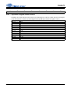
V_PCM_BIT_ORDER VSP_SDOUT/VSP_SDIN Bit Order
0 MSB to LSB
1 LSB to MSB
Application: Refer to section “PCM Format” on page 55.