
Instruction Manual


70 DS882F1
CS42L73
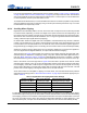
4.14 Headphone Plug Detect and Mic Short Detect
To implement “headphone plug detect,” a suitable jack and system GPIO are required. Figure 35 shows two
common implementations of headphone plug using additional pins within the jack. Jack detect pin type B
(refer to Figure 35) is preferred, because type A requires additional filtering to remove signal from the
HPOUTA pin when the headset is disconnected.
Note that Figure 35 shows one possible configuration of TRRS (Tip, Ring 1, Ring 2, Sleeve) signaling re-
garding ring 2 and sleeve. Some headsets in the marketplace use an alternate pinout and assign the mic
signal to sleeve and ground to ring 2. The decision of which headset type to support must be made in hard-
ware, as the CS42L73 does not support detection of or automatic reconfiguring of the pins for alternate
headset pinout assignments.
Microphone short detect is accomplished using the internal detect feature of the CS42L73. Connect the
short detect pin as shown in Figure 35. Next, set register 0x5E bit 6 = 1. If no other state change other than
MIC2_SDET
is required to trigger the INT pin, the value of register 0x5E may be set to 0x40. This unmasks
the MIC2_SDET status bit (register 0x60 bit 6) so that the INT
pin will be driven low or pulled high based on
the MIC2_SDET
status bit.
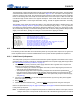
With the system connected and registers configured as described above, the CS42L73 will drive the INT
pin
low when a high-to-low transition on MIC2_SDET
is detected (indicating the mic short button has been
pressed). The INT
pin will also be driven low when a low-to-high transition on MIC2_SDET is detected (in-
dicating the button has been released). The INT
pin will remain low unless register 0x60 is read; reading
register 0x60 sets the INT
pin high. The MIC2_SDET state (shorted or not shorted) can be read via register
0x60 bit 6 at any time.
The flow diagram in Figure 34 summarizes the behavior of the INT
pin when Register 0x5E = 0x40.
4.15 Interrupts
The CS42L73 includes an open-drain, active-low interrupt output. The registers “Interrupt Mask Register 1
(Address 5Eh)” on page 122 and “Interrupt Mask Register 2 (Address 5Fh)” on page 122 must be used to
unmask any interrupt status bits (registers “Interrupt Status Register 1 (Address 60h)” on page 122 and “In-
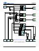
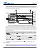
Figure 35. Connection Diagram for Headphone Detect with Additional Short Detect
Jack Detect Pin B
Tip
Ring 1
Sleeve
100 33 nF
100 33 nF
HPOUT_REF
HPOUTB
HPOUTA
MIC2_SDET
INT
VL Supply
2 k
To System
Microcontroller
Jack Detect Pin A
Ring 2
MIC2
0.1 F
MIC2_BIAS
1 F
2.21 k
MIC2_REF
0.1 F
VL Supply
47 k