
Instruction Manual


68 DS882F1
CS42L73
1. The CS42L73 must be put into a powered down state using the procedure in section “Power-Down
Sequence (xSP to HP/LO)” on page 67.
2. The MCLK signal may then be modified or disabled at its external source (when applicable), and/or
changes to the related CS42L73 control registers (see register controls list below) can be made. Use
the procedure in section “Power-Up Sequence (xSP to HP/LO)” on page 66 to bring the CS42L73 out
of the powered down state.
Register Controls: MCLKSEL, MCLKDIV, and MCLKDIS
4.12.5 Microphone Enabling/Switching Sequence
When the microphone inputs are enabled or disabled, temporary disturbances will occur on them. In ad-
dition, switching the PGA Mux will cause an audible discontinuity disturbance. To avoid the transmission
of these disturbances, the following procedure must be used.
1. Mute the ADC output (Input Path Digital) with the soft mute enabled if it is not already muted, and wait
until the ADC is fully muted (mute soft-ramp rate is defined in register description “Digital Soft-Ramp”
on page 96). Note for initializing the Microphone soft-ramp enable of mute is not necessary.
Register Controls: IPxMUTE and DIGSFT
2. Enable and/or disable the MIC bias outputs as desired and wait until all MIC inputs have stabilized
(about 20 ms for C
INM
= 1 F; refer to “Typical Connection Diagram” on page 17).
Register Controls: PDN_MICx_BIAS
3. If desired, switch the input to the ADC (MICx/LINEx).
Register Controls: PGAxMUX
4. Soft-release ADC mute.
4.12.6 Final Power-Down Sequence
The final power-down sequence must be executed before removing the power for the CS42L73.
1. If not already completed, follow the sequence specified in “Power-Down Sequence (xSP to HP/LO)”
on page 67 and the disable steps of “Microphone Enabling/Switching Sequence” on page 68. If other
audio paths are active in the CS42L73, use a similar approach to avoid pops and properly shutdown
each sub-block of the device.
2. Power down the CS42L73 by setting register bit PDN = 1. If step 1 is not followed a wait of 50 ms is
recommended before proceeding.
3. To minimize pops and clicks when the power supplies are pulled to ground, it is recommended that
the DISCHG_FILT bit is set before the supplies are pulled to ground. This will discharge the
recommended 2.2 µF FILT+ capacitor within approximately 10 ms.
Register Controls: DISCHG_FILT
4. Set RESET
low (active).
5. Wait the specified setup time (t
rs(RL-PWR)
) before lowering the power supply rails to less than the
minimum recommended operating voltages (specified in spec. table “Recommended Operating
Conditions” on page 19).
6. Continue to hold RESET
low at least until all the power supplies have ramped down to ground.
– Ensure the ramping-down of each of the supplies is smooth (no up-slope regions) and does not
take longer than the specified time (t
pwr-rud
).
– The last power supply rail to reach ground must do so within the specified time (t
pwr-rs
) from when
the first power rail reaches ground. Exception: the VP supply may be applied or removed
independently of RESET
and the other power rails (except for the VA supply, see (Note 4)).
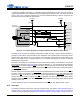
Refer to Section on page 36, and Figure 10 on page 36 to find the durations referenced in this pow-
er-down sequence.