
Instruction Manual


40 DS882F1
CS42L73
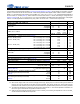
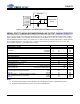
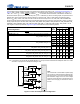
SWITCHING SPECIFICATIONS—CONTROL PORT
Test conditions: Inputs: Logic 0 = GND = DGND = 0 V, Logic 1 = VL; T
A
= +25 C; SDA load capacitance equal to maximum
value of C
b
specified below (Note 58); minimum SDA pull-up resistance (R
P(min)
) (Note 51).
Notes:
58. All specifications are valid for the signals at the pins of the CS42L73 with the specified load capacitance.
59. Data must be held for sufficient time to bridge the transition time, t
f
, of SCL.
Parameters (Note 2) Symbol Min Max Unit
RESET Rising Edge to Start (Note 52) t
irs
500 - ns
SCL Clock Frequency
f
scl
- 550 kHz
Start Condition Hold Time (prior to first clock pulse)
t
hdst
0.6 - µs
Clock Low time
t
low
1.3 - µs
Clock High Time
t
high
0.6 - µs
Setup Time for Repeated Start Condition
t
sust
0.6 - µs
SDA Input Hold Time from SCL Falling (Note 59)
t
hddi
00.9µs
SDA Output Hold Time from SCL Falling
t
hddo
0.2 0.9 µs
SDA Setup Time to SCL Rising
t
sud
100 - ns
Rise Time of SCL and SDA
t
r
- 300 ns
Fall Time SCL and SDA
t
f
- 300 ns
Setup Time for Stop Condition
t
susp
0.6 - µs
Bus Free Time Between Transmissions
t
buf
1.3 - µs
SDA Bus Load Capacitance (Note 51)
C
b
- 400 pF
t
buf
t
hdst
t
hdst
t
low
t
r
t
f
t
hdd
t
high
t
sud
t
sust
t
susp
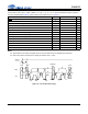
Stop Start
Start
Stop
Repeated
SDA
SCL
t
irs
RESET
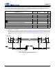
Figure 14. I²C Control Port Timing