
Instruction Manual


32 DS882F1
CS42L73
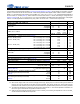
SERIAL PORT TO MONO SPEAKERPHONE LINE OUTPUT CHARACTERISTICS
Test conditions (unless otherwise specified): Connections to the CS42L73 are shown in the “Typical Connection Diagram” on
page 17; Input test signal is a 24-bit full-scale 997-Hz sine wave with 1 LSB of triangular PDF dither applied; GND = AGND =
PGND = CPGND = DGND = 0 V; all voltages are with respect to ground (GND); VA = 1.80 V, VP = 3.70 V; T
A
= +25 C; Mea-
surement Bandwidth is 20 Hz to 20 kHz; Fs = 48 kHz (Note 10); ASP is used and is in slave mode with Fs
ext
= 48 kHz; test load-
ing is configured as per Figure 8 on page 32 (R
L
, C
L1
, and C
L2
as indicated in the table below for R
L(Typ)
, C
L1(Max)
, and
C
L2(Max)
); Mixer Attenuation = 0 dB, Digital Mute is disabled.
Notes:
45. The full-scale output voltage includes attenuation due to the Speakerphone Line Output Resistance (R
OUT
).
46. The specified output resistance is present on each of the SPKLINEO pins.
Parameters (Note 2) Min Typ Max Units
Digital Volume = -5.5 dB
Dynamic Range
16 to 24-Bit A-weighted
unweighted
78
75
84
81
-
-
dB
dB
Total Harmonic Distortion + Noise (Note 39) (Note 42), 16 to 24-Bit 0 dBFS
--65-60dB
Full-scale Output Voltage (Note 39) (Note 45) (Diff. SPKLINEO±, see Note 40)
2.97•VA 3.21•VA 3.45•VA V
PP
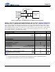
Other Characteristics
Output Offset Voltage (DC offset of diff. SPKLINEO±, see Note 40)
- ±5.0 ±10.0 mV
Gain Drift
- ±100 - ppm/°C
Output Resistance (R
OUT
) (Note 46)
- 100 -
Load Resistance (R
L
) (Note 41)
350-k
Load Capacitances C
L1
across outputs/load
(Note 41) (Note 43) C
L2
from each output to ground
-
-
-
-
150
50
pF
pF
PSRR with 100 mV
PP
signal AC-coupled to VA supply 217 Hz
–Input test signal held low (all zeros data) 1 kHz
(Note 36) 20 kHz
-
-
-
70
70
70
-
-
-
dB
dB
dB
PSRR with 100 mV
PP
signal AC-coupled to VP supply 217 Hz
–Input test signal held low (all zeros data) 1 kHz
(Note 44) 20 kHz
-
-
-
70
80
75
-
-
-
dB
dB
dB
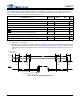
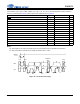
Test Load
SPKOUT+
or SPKLINEO+
PGND/AGND
R
L
SPKOUT-
or SPKLINEO-
C
L2
C
L2
C
L1
Measurement
Device
-
+
Figure 8. Speakerphone and Speakerphone Line Output Test Configuration