
Instruction Manual

DS882F1 25
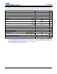
CS42L73
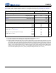
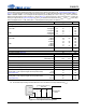
THERMAL OVERLOAD DETECT CHARACTERISTICS
Test Conditions: Connections to the CS42L73 are shown in the “Typical Connection Diagram” on page 17; GND = AGND =
PGND = CPGND = DGND = 0 V; all voltages are with respect to ground (GND); VA = 1.80 V.
Notes:
23. The thermal overload detect threshold temperature level can vary from the nominal value by ±10 °C.
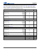
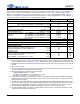
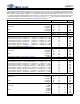
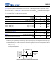
ASRC DIGITAL FILTER CHARACTERISTICS
Test Conditions (unless otherwise specified): Fs = 48 kHz (Note 10); Fs
ext
= 48 kHz (Note 24).
Notes:
24. Fs
ext
is the sample rate of the serial port (XSP, ASP, or VSP) interface.
25. Refer to Response plots in Figures 53 and 54 on page 129.
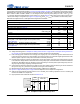
26. The equations for the group delay through the sample rate converters are:
• Input (from the serial ports to the core): 6.9/Fs
ext
+ 3.0/Fs
• Output (from the core to the serial ports): 2.6/Fs
ext
+ 14.1/Fs.
A plot of ASRC group delay values for the extreme supported internal sample rates (Fs) and standard audio sample
rates is found in section “Group Delay” on page 130.
Parameters Min Typ Max Units
Thermal Overload Detect Threshold Characteristics
Threshold Junction Temperature (T
J
) (Note 23) THMOVLD_THLD[1:0] = 00b
THMOVLD_THLD[1:0] = 01b
THMOVLD_THLD[1:0] = 10b
THMOVLD_THLD[1:0] = 11b
-
-
-
-
150
132
115
98
-
-
-
-
°C
°C
°C
°C
Parameters (Note 2) (Note 25) Min Typ Max Units
Low-Pass Filter Characteristics (Note 24)
Frequency Response (0 Hz to 20 kHz)
-0.07 - +0.04 dB
Passband to -0.05 dB corner
to -3.0 dB corner
-
-
0.48
0.50
-
-
Fs
ext
Stopband
0.55 - - Fs
ext
Stopband Attenuation
125 - - dB
Total ASRC Group Delay
- (Note 26) -s