
Instruction Manual

DS882F1 23
CS42L73
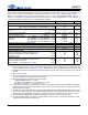
Notes:
10. Fs is the sampling frequency used by the core and the A/D and D/A converters. For specifications, a default value of 48
kHz is used. Refer to section “Applications” on page 41 for a description of how Fs relates to the CS42L73‘s clock inputs.
11. Measures are referred to the applicable typical full-scale voltages. Applies to all THD+N and dynamic range values in
the table.
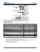
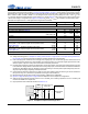
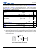
12. Refer to Figure 3 below.
13. Includes noise from MICx_BIAS output through series 2.21 kseries resistor to MICx. Refer to Figure 2 below. Input
signal is -60 dB down from corresponding full-scale voltage.
14. Measurement taken with the following analog gain settings:
• LINEINA/LINEINB: PGAxVOL = +12 dB
• MIC1/MIC2: MIC_PREAMPx= + 20 dB, PGAxVOL = +12 dB
• HPxAVOL = +2 dB for R
L
= 3 k, -4 dB for R
L
= 16
15. The full-scale input voltages given refer to the maximum voltage difference between the LINEINx/MICx and LINEIN_
REF/MICx_REF pins. Providing an input signal at these pins that exceeds the full-scale input voltage will result in the
clipping of the analog signal.
16. The PGA output clips if the voltage difference between the LINEINx/MICx and LINEIN_REF/MICx_REF signals exceeds
the full-scale voltage specification. If the LINEIN_REF/MICx_REF signal level exceeds the specified maximum value,
PGA linearity may be degraded and analog input performance may be adversely affected. Refer to Figure 4 below.
17. Measured between LINEINx/MICy and AGND. Input impedance can vary from nominal value by ±20%.
18. The PGA is biased with ANA_VQ, created by a resistor divider from the VA supply. Increasing the capacitance on ANA_
VQ will increase the PSRR at low frequencies.
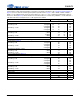
Input
Interchannel Isolation (1 kHz) LINEINA to LINEINB, PGAxVOL = +12 dB
MIC1 to MIC2, MIC_PREAMPx = +20 dB, PGAxVOL = +12 dB
-
-
90
80
-
-
dB
HP Amp to Analog Input Isolation R
L
= 3 k
(Note 14) R
L
= 16
84
77
90
83
-
-
dB
dB
Full-scale Signal Input Voltage PGAxVOL = 0 dB
LINEINA/LINEINB (Note 15) PGAxVOL = +12 dB
0.78•VA
-
0.82•VA
0.198•VA
0.86•VA
-
V
PP
V
PP
Full-scale Signal Input Voltage MIC_PREAMPx = +10 dB, PGAxVOL = +0 dB
MIC1/MIC2 MIC_PREAMPx = +20 dB, PGAxVOL = +0 dB
(Note 15) MIC_PREAMPx = +10 dB, PGAxVOL = +12 dB
MIC_PREAMPx = +20 dB, PGAxVOL = +12 dB
-
-
-
-
0.258•VA
0.081•VA
0.064•VA
0.020•VA
-
-
-
-
V
PP
V
PP
V
PP
V
PP
LINEIN_REF/MICx_REF Input Voltage (Note 16)
- - 0.300 V
PP
Input Impedance (Note 17), LINEINA/LINEINB 1 kHz
-50-k
Input Impedance (Note 17), MIC1/MIC2 1 kHz
-1.0-M
DC Voltage at Analog Input (Pin Floating)
- 0.50•VA - V
LINEINA/LINEINAB PSRR
- 100 mV
PP
signal AC-coupled to VA supply (Note 18) 217 Hz
- LINEINA and LINEINB connected to LINEIN_REF 1 kHz
- PGAxVOL = 0 dB 20 kHz
-
-
-
50
65
40
-
-
-
dB
dB
dB
MIC1/MIC2 PSRR
- 100 mV
PP
signal AC-coupled to VA supply (Note 18) 217 Hz
- MICx connected to MICx_REF 1 kHz
- MIC_PREAMPx = +20 dB, PGAxVOL = +12 dB 20 kHz
-
-
-
50
65
35
-
-
-
dB
dB
dB
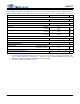
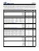
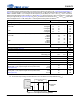
ANALOG INPUT TO SERIAL PORT CHARACTERISTICS (CONTINUED)
Test Conditions (unless otherwise specified): Connections to the CS42L73 are shown in the “Typical Connection Diagram” on
page 17; Input is a 1-kHz sine wave through the passive input filter shown in Figure 1; GND = AGND = PGND = CPGND =
DGND = 0 V; all voltages are with respect to ground (GND); VA = 1.80 V; T
A
= +25 C; Measurement Bandwidth is 20 Hz to
20 kHz; Fs = 48 kHz (Note 10); ASP is used and is in slave mode with Fs
ext
= 48 kHz; MIC_PREAMPx = +10 dB, PGAxVOL =
0 dB; Mixer Attenuation and Digital Volume = 0 dB, Digital Mute is disabled.
Parameters (Note 2) (Note 11) Min Typ Max Units