
Instruction Manual

136 DS882F1
CS42L73
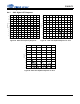
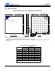
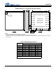
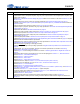
10.2 FBGA Package
65-Ball FBGA (5 x 5 mm Body) Package Drawing
Table 18. FBGA Package Dimensions
Dimension
Millimeters
Minimum Nominal Maximum
A 0.74 0.87 1.00
A1 0.16 0.21 0.26
A2 0.58 0.66 0.74
M BSC 4.00 BSC
N BSC 4.00 BSC
b 0.27 0.30 0.37
c REF 0.50 REF
d REF 0.50 REF
e BSC 0.50 BSC
X 4.90 5.00 5.10
Y 4.90 5.00 5.10
ccc = 0.05
ddd = 0.15
Note: Controlling dimension is millimeters.
e
e
A2
Ball A1
Location
Indicator
X
Y
BUMP SIDESIDE VIEW
A1
N
M
d
c
TOP SIDE
Ball A1 Location Indicator
Ball A1
A
b
Seating plane
X
Z
Y
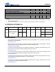
Notes:
• Dimensioning and tolerances per ASME Y 14.5M–1994.
• The Ball A1 position indicator is for illustration purposes only and may not be to scale.
• Dimension “b” applies to the solder sphere diameter and is measured at the midpoint between the package body and the seating
plane Datum Z.
øb
Øddd Z X Y
Øccc Z