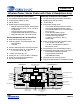
CS42L56 Ultralow Power, Stereo Codec with Class H Headphone Amp DIGITAL to ANALOG FEATURES ANALOG to DIGITAL FEATURES 5 mW Stereo Playback Power Consumption 3.
CS42L56 SYSTEM FEATURES Audio (11.2896 MHz or 12.288 MHz) or USB (12 MHz) Master Clock Input Low-power Operation – Stereo Anlg. Passthrough: 3.3 mW @1.8 V – Stereo Rec. and Playback: 8.3 mW @1.
CS42L56 TABLE OF CONTENTS 1. PIN DESCRIPTIONS .............................................................................................................................. 8 1.1 I/O Pin Characteristics .................................................................................................................... 10 2. TYPICAL CONNECTION DIAGRAMS ................................................................................................. 11 3. CHARACTERISTIC AND SPECIFICATION TABLES ..............
CS42L56 4.11.2 Power-Down Sequence ....................................................................................................... 50 4.12 Recommended PGA to HP or Line Power Sequence (Analog Passthrough) .............................. 51 4.12.1 Power-Up Sequence ........................................................................................................... 51 4.12.2 Power-Down Sequence ......................................................................................................
CS42L56 6.11.2 HP/Line De-Emphasis ......................................................................................................... 65 6.11.3 Playback Channels B=A ...................................................................................................... 65 6.11.4 Invert PCM Signal Polarity .................................................................................................. 65 6.12 DSP Mute Controls (Address 0Ch) ............................................................
CS42L56 6.27.1 PGA x Input Select .............................................................................................................. 76 6.27.2 PGAx Volume ...................................................................................................................... 77 6.28 ADCx Attenuator Control: ADCAATT (Address 20h) & ADCBATT (Address 21h) ....................... 77 6.28.1 ADCx Volume .....................................................................................................
CS42L56 LIST OF FIGURES Figure 1.Typical Connection Diagram - Four Pseudo-Differential Analog Inputs ...................................... 11 Figure 2.Typical Connection Diagram - Two Pseudo-Differential / Three Single-Ended Analog Inputs ... 12 Figure 3.Typical Connection Diagram - Six Single-Ended Analog Inputs ................................................. 13 Figure 4.CMRR Test Configuration ...........................................................................................................
CS42L56 Pin Name SDIN SCLK MCLK SDOUT VL VDFILT VLDO RESET HPDETECT AIN2B AIN2REF/AIN3B 40 39 38 37 36 35 34 33 32 31 1.
CS42L56 -VHPFILT 11 Inverting Charge Pump Filter Connection (Output) - Power supply from the inverting charge pump that provides the negative rail for the headphone and line amplifiers. HPOUTA HPOUTB 12 14 Headphone Audio Output (Output) - The full-scale output level is specified in “HP Output Characteristics” on page 19. HPREF 13 Pseudo Diff.
CS42L56 1.1 I/O Pin Characteristics Input and output levels and associated power supply voltage are shown in the table below. Logic levels should not exceed the corresponding power supply voltage.
CS42L56 2. TYPICAL CONNECTION DIAGRAMS 1 µF ** ** VDFILT 0.1 µF VLDO ** +1.65 V to +2.75 V 0.1 µF VA 47 k HPREF Note 1 +VHPFILT ** 2.2 µF HPOUTB HPOUTA ** 33 Headphone Out Left & Right 33 ** 0.1 µF Note 1 +1.65 V to +2.75 V HPDETECT VCP 2.2 µF 0.1 µF ** CS42L56 Note 2 2.2 µF ** 2. 2 µF ** FLYP LINEOUTA FLYC LINEOUTB Note 1 ** 3300 pF Rext LPF is Optional * LINEREF FLYN 2.
CS42L56 1 µF 1 µF ** ** ** VDFILT VDFILT 0.1 µF **0.1 µF ** VLDO VLDO VA +1.65 V to +2.75 V 0.1 µF +1.65 V to +2.75 V ** µF 0.1 VA 47 k HPREF HPREF Note 1 Note 1 2.2 µF 0.1 µF 0.1 µF +VHPFILT +VHPFILT ** ** 2.2 µF ** 33 ** HPOUTB HPOUTB HPOUTA HPOUTA ** +1.65 V to +2.75 V CS42L56 LINEOUTA 2.2 µF ** 2.2 µF ** 2. 2 µF ** FLYP FLYP 2.
CS42L56 1 µF ** ** VDFILT 0.1 µF VLDO ** +1.65 V to +2.75 V 0.1 µF VA 47 k HPREF 0.1 µF +VHPFILT Note 1 ** 2.2 µF HPOUTB HPOUTA ** 33 Headphone Out Left & Right 33 ** 0.1 µF Note 1 +1.65 V to +2.75 V VCP 2.2 µF ** HPDETECT CS42L56 LINEOUTA Note 2 2.2 µF ** 2.2 µF ** 562 3300 pF FLYP LINEOUTB FLYC R ext LPF is Optional * LINEREF R ext * 3300 pF Line Level Out Left & Right 562 FLYN 2.
CS42L56 3. CHARACTERISTIC AND SPECIFICATION TABLES RECOMMENDED OPERATING CONDITIONS GND = AGND = 0 V; all voltages with respect to ground. Parameters DC Power Supply Analog Charge Pump LDO Regulator for Digital Serial/Control Port Interface Ambient Temperature (Note 1) (Note 1) Commercial - CNZ Symbol Min Max Units VA VCP VLDO VL TA 1.62 1.62 1.62 1.62 -40 2.75 VA 2.75 3.63 +85 V V V V C ABSOLUTE MAXIMUM RATINGS GND = AGND = 0 V; all voltages with respect to ground.
CS42L56 ANALOG INPUT CHARACTERISTICS (CONTINUED) Test Conditions (unless otherwise specified): Connections to the CS42L56 are shown in the “Typical Connection Diagrams” on page 11; Input test signal is a 1 kHz sine wave through the passive input filter, PGA = 0 dB; All Supplies = VA; GND = AGND = 0 V; TA = +25C; Measurement bandwidth is 20 Hz to 20 kHz; Sample Frequency = 48 kHz. Measurement signal path is AINxx to SDOUT.
CS42L56 ANALOG INPUT CHARACTERISTICS (CONTINUED) Test Conditions (unless otherwise specified): Connections to the CS42L56 are shown in the “Typical Connection Diagrams” on page 11; Input test signal is a 1 kHz sine wave through the passive input filter, PGA = 0 dB; All Supplies = VA; GND = AGND = 0 V; TA = +25C; Measurement bandwidth is 20 Hz to 20 kHz; Sample Frequency = 48 kHz. Measurement signal path is AINxx to SDOUT. Full-scale Signal Input Voltage (Note 8) ADC 0.76•VA 0.80•VA 0.84•VA 0.76•VA 0.
CS42L56 ADC DIGITAL FILTER CHARACTERISTICS Parameter (Note 11) Frequency Response (20 Hz to 20 kHz) Passband to -0.05 dB corner to -3 dB corner Stopband Stopband Attenuation Total Group Delay High-Pass Filter Characteristics (48 kHz Fs) (Note 12) Passband to -3.0 dB corner to -0.05 dB corner Frequency Response Phase Deviation @ 20 Hz Filter Settling Time (Note 13) Min Typ Max Unit -0.07 0.52 33 - 0.421 0.495 4.3/Fs +0.02 - dB Fs Fs Fs dB s - 1.87 17.15 5.3 0.
CS42L56 HP OUTPUT CHARACTERISTICS Test conditions (unless otherwise specified): Connections to the CS42L56 are shown in the “Typical Connection Diagrams” on page 11; Input test signal is a full-scale 997 Hz sine wave; All Supplies = VA, VCP Mode; GND = AGND = 0 V; TA = +25C; Measurement bandwidth is 20 Hz to 20 kHz; Sample Frequency = 48 kHz; Test load RL = 10 k CL = 150 pFfor a line load, and test load RL = 16 CL = 150 pF for a headphone load (See Figure 6 on page 21); Measurement signal path is SDI
CS42L56 LINE OUTPUT CHARACTERISTICS Test conditions (unless otherwise specified): Connections to the CS42L56 are shown in the “Typical Connection Diagrams” on page 11; Input test signal is a full-scale 997 Hz sine wave; All Supplies = VA, VCP Mode; GND = AGND = 0 V; TA = +25C; Measurement bandwidth is 20 Hz to 20 kHz; Sample Frequency = 48 kHz; Test load RL = 10 k CL = 150 pF (see Figure 6 on page 21); Measurement signal path is SDIN to LINEOUTx. VA = 2.
CS42L56 Test Load Symbolized component values are specified in table “HP Output Characteristics” on page 19 HPOUTx HPREF GND/AGND 33 CL RL 0.1 µF + Measurement Device Figure 6. HP Output Test Configuration Symbolized component values are specified in table “Line Output Characteristics” on page 20 Test Load LINEOUTx CL RL LINEREF GND/AGND + Measurement Device Figure 7.
CS42L56 ANALOG PASSTHROUGH CHARACTERISTICS Test Conditions (unless otherwise specified): Connections to the CS42L56 are shown in the “Typical Connection Diagrams” on page 11; Input test signal is a 1 kHz sine wave through the passive input filter shown in Figure 1, PGA and HP/Line gain = 0 dB; All Supplies = VA, VCP Mode; GND = AGND = 0 V; TA = +25C; Measurement bandwidth is 20 Hz to 20 kHz; Sample Frequency = 48 kHz; Measurement signal path is AINxx to HPOUTx or LINEOUTx.
CS42L56 SWITCHING SPECIFICATIONS - SERIAL PORT Inputs: Logic 0 = GND = AGND, Logic 1 = VL, LRCK, SCLK, SDOUT CLOAD = 15 pF.
CS42L56 SWITCHING SPECIFICATIONS - I²C CONTROL PORT Inputs: Logic 0 = GND = AGND, Logic 1 = VL (Note 22) . Parameter Symbol Min Max Unit tirs 500 - ns RESET Rising Edge to Start SCL Clock Frequency fscl - 550 kHz Start Condition Hold Time (prior to first clock pulse) thdst 0.6 - µs Clock Low Time tlow 1.3 - µs Clock High Time thigh 0.6 - µs tsust 0.6 - µs thddi 0 0.
CS42L56 SWITCHING CHARACTERISTICS - SPI CONTROL PORT Inputs: Logic 0 = GND = AGND, Logic 1 = VL, SDA CL = 30 pF. Parameter Symbol Min Max Units CCLK Clock Frequency fsck 0 6.0 MHz RESET Rising Edge to CS Falling tsrs 20 - ns CS Falling to CCLK Edge tcss 20 - ns CS High Time Between Transmissions tcsh 1.
CS42L56 ANALOG OUTPUT ATTENUATION CHARACTERISTICS Test Conditions (unless otherwise specified): Connections to the CS42L56 are shown in the “Typical Connection Diagrams” on page 11; GND = AGND = 0 V. Attenuation is referenced to the full-scale voltage for the given output. Test load RL = 3 k CL = 150 pFfor a line load, and test load RL = 16 CL = 150 pF for a headphone load (See Figure 6 and Figure 7 on page 21).
CS42L56 DC CHARACTERISTICS Test Conditions (unless otherwise specified): Connections to the CS42L56 are shown in the “Typical Connection Diagrams” on page 11; GND = AGND = 0 V; all voltages with respect to ground. Parameters Min Typ Max Units VHPFILT Characteristics (Note 27) VCP Mode +VHPFILT -VHPFILT - VCP -VCP - V V VCP/2 Mode +VHPFILT -VHPFILT - VCP/2 -VCP/2 - V V BIAS_LVL[1:0] = 00 BIAS_LVL[1:0] = 01 BIAS_LVL[1:0] = 10 BIAS_LVL[1:0] = 11 - 0.9•VA 0.8•VA 0.7•VA 0.
CS42L56 DIGITAL INTERFACE SPECIFICATIONS & CHARACTERISTICS Parameters (Note 31) Symbol Min Max Units Iin - ±10 10 A pF 1.8 V - 3.3 V Logic High-Level Output Voltage (IOH = -100 A) VOH VL - 0.2 - V Low-Level Output Voltage (IOL = 100 A) VOL - 0.2 V 0.30•VL V V 0.35•VA V V Input Leakage Current Input Capacitance High-Level Input Voltage VL = 1.65 V VL = 1.8 V VL = 2.0 V VL > 2.0 V Low-Level Input Voltage VIL 0.83•VL 0.76•VL 0.68•VL 0.
CS42L56 POWER CONSUMPTION - ALL SUPPLIES = 1.
CS42L56 POWER CONSUMPTION - ALL SUPPLIES = 2.
CS42L56 4. APPLICATIONS 4.1 4.1.1 Overview Basic Architecture The CS42L56 is a highly integrated, ultra-low power, 24-bit audio CODEC comprised of stereo A/D and D/A converters with pseudo-differential stereo input and output amplifiers. The ADC and DAC are designed using multi-bit delta-sigma techniques; both converters operate at a low oversampling ratio of 64xFs, maximizing power savings while maintaining high performance.
CS42L56 4.
CS42L56 4.2.1 Pseudo-differential Inputs The CS42L56 implements a pseudo-differential input stage. The AINxREF inputs are intended to be used as a pseudo-differential reference signal. This feature provides common mode noise rejection with singleended signals. Figure 14 shows a basic diagram outlining the internal implementation of the pseudo-differential input stage, including a recommended stereo pseudo-differential input topology.
CS42L56 If signals larger than what is shown in Table 1 are needed, an external resistor divider should be used as shown in Table 15. When using an external resistor divider, the PGA must be configured to be in-circuit. R1 1 µF Input AINxx R3 R2 Figure 15. Analog Input Attenuation Three parameters determine the values of resistors R1 and R2 as shown in Figure 15: source impedance, attenuation, and input impedance. Table 2 shows the design equation used to determine these values.
CS42L56 4.2.3 Microphone Inputs Any of the line inputs can be configured as a microphone input by using the MICBIAS pin to power the external microphone circuit and by configuring the additional +10 or +20 dB gain in the PGA to properly boost the low-level microphone signal. 4.2.3.1 External Passive Components The analog inputs are internally biased to VQ. Input signals must be AC coupled using external capacitors with values consistent with the desired high-pass filter design.
CS42L56 whenever a threshold violation occurs. It then modifies the signal level by adjusting the gain settings in the PGA and ADC digital volume control accordingly. As shown in Figure 18, if the input signal level rises above the maximum threshold, the ALC first lowers the PGA gain settings. It then decreases the ADC digital volume at a programmable “attack” rate and maintains the resulting level below the maximum threshold.
CS42L56 4.2.5.1 Attack/Release Time Calculations: The time taken by the ALC to perform an attack or a release operation is a function of the PGA/ADC digital volume control gain settings, ADC soft ramp/zero-cross settings, sample rate (Fs), maximum/minimum threshold settings, attack/release rate settings and the signal level after the digital volume control block.
CS42L56 4.4 Analog Outputs INPUTS FROM ADCA and ADCB Fixed Function DSP MSTAVOL[7:0] MSTBVOL[7:0] AMIXAMUTE AMIXBMUTE AMIXAVOL[6:0] AMIXBVOL[6:0] VOL PCM Serial Interface PMIXAMUTE PMIXBMUTE PMIXAVOL[6:0] PMIXBVOL[6:0] Demph DEEMPH VOL LIMARATE[7:0] LIMRRATE[7:0] LMAX[2:0] CUSH[2:0] LIMSRDIS LIMIT LIMIT_ALL Channel Swap Chnl Vol.
CS42L56 VCP Step-down/Inverting Charge Pump ADPTPWR[1:0] Class H Control = HP and Line Supply HP Detection +VCP +VCP/2 HPDETECT PDN_HPx[1:0] PDN_LINx[1:0] -VCP -VCP/2 +VHPFILT CHGFREQ[3:0] +HP Supply from PGAx from DACx +Line Supply HPOUTA HPOUTB - HPxMUX HPxVOL[6:0] HPxMUTE ANLGZC PLYBCKB=A + HPREF LINEOUTA LINEOUTB + LINExMUX LINExVOL[6:0] LINExMUTE ANLGZC PLYBCKB=A LINEREF -HP Supply -Line Supply -VHPFILT Figure 20. Analog Output Stage 4.
CS42L56 4.5.1 Power Control Options The method by which the CS42L56 decides which set of rail voltages is supplied to the amplifier output stages depends on the settings of the Adaptive Power bits (ADPTPWR) found in “Class H Control (Address 08h)” section on page 63. As detailed in this section, there are four possible settings for these bits: standard Class AB mode (settings 01 and 10), adapt to volume mode (setting 00) and adapt to signal (setting 11).
CS42L56 ume setting should be factored in with the volume settings of other control blocks in the signal path. The Class H controller can be affected by the combined effect of all the volume settings in the relevant path or the maximum sum in each channel (A, B) and the maximum sum in each amplifier (HP, Line). To determine the correct rail voltage for the amplifier, the controller assumes the input advisory volume is set correctly and that the signal level in each processing block does not exceed 0 dB.
CS42L56 of Line Path = Effect of Volume Sum in HP or Line Paths of HP Path = case2 HP/LINE Supply Decision: VCP VCP/2 Case 2 Result Case 1 Result -10.5 dB -10. 5 dB case1 case1 Since the HP and the Line amplifiers also share the same supply, the explanation above applies to the total gain/attenuation set in the HP and Line amplifiers. If enabled, the volume settings in the path of both amplifiers are considered before the charge pump supplies the appropriate rail voltage.
CS42L56 4.5.1.3 Adapt to Output Mode (setting 11) When the Adaptive Power bits are set to 11, the CS42L56 decides which of the two sets of rail voltages to send to the amplifiers based solely upon the level of the signal being sent to the amplifiers. If the signal that is sent to the amplifiers would cause the amplifiers to clip when operating on the lower set of rail voltages, the control logic instructs the charge pump to provide the higher set of rail voltages (±VCP) to the amplifiers.
CS42L56 Output Level 1 second -10 dB Time Amplifier Rail Voltage VCP VCP 2 Time - VCP 2 - VCP Figure 26. VHPFILT Hysteresis 4.5.3 Efficiency As discussed in previous sections, the amplifiers internal to the CS42L56 operate from one of two sets of rail voltages, based upon the needs of the signal being amplified or the total gain/attenuation settings. The power curves for the two modes of operation are shown in Figure 27 and Figure 28.
CS42L56 When the rail voltages are set to VCP, the amplifiers will operate in their least efficient mode. When the rail voltages are held at ±VCP/2, the amplifiers will operate in their most efficient mode, but will be clipped if required to amplify a full-scale signal. Note: The ±VCP/2 curve ends at the point at which the output of the amplifiers reaches 10% THD+N. The benefit of Bi-Modal Class H is shown in the solid trace on the graph. At lower output levels, the amplifiers operate on the ±VCP/2 curve.
CS42L56 BEEP[1:0] = '11' CONTINUOUS BEEP: Beep turns on at a configurable frequency (FREQ) and volume (BPVOL) and remains on until REPEAT is cleared. BEEP[1:0] = '10' MULTI-BEEP: Beep turns on at a configurable frequency (FREQ) and volume (BPVOL) for the duration of ONTIME and turns off for the duration of OFFTIME. On and off cycles are repeated until REPEAT is cleared. BEEP[1:0] = '01' SINGLE-BEEP: Beep turns on at a configurable frequency (FREQ) and volume (BPVOL) for the duration of ONTIME.
CS42L56 Input MAX[2:0] Limiter ATTACK/RELEASE SOUND CUSHION Volume Output (after Limiter) CUSH[2:0] MAX[2:0] ARATE[5:0] RRATE[5:0] Figure 30. Peak Detect & Limiter 4.8 Serial Port Clocking The CODEC serial audio interface port operates either as a slave or master. It accepts externally generated clocks in Slave Mode (M/S = 0b) and will generate synchronous clocks derived from an input master clock (MCLK) in Master Mode (M/S = 1b).
CS42L56 MCLK (MHz) 24.0000 (MKPREDIV=1b) (MCLKDIV2=1b) 12.0000 (MKPREDIV=0b) (MCLKDIV2=1b) 6.0000 (MKPREDIV=0b) (MCLKDIV2=0b) 24.5760 (MKPREDIV=1b) (MCLKDIV2=1b) 12.2880 (MKPREDIV=0b) (MCLKDIV2=1b) 6.1440 (MKPREDIV=0b) (MCLKDIV2=0b) LRCK (kHz) 8.0000 11.0294 12.0000 16.0000 22.0588 24.0000 32.0000 44.1180 48.0000 8.0000 11.0294 12.0000 16.0000 22.0588 24.0000 32.0000 44.1180 48.0000 8.0000 11.0294 12.0000 16.0000 22.0588 24.0000 32.0000 44.1180 48.0000 8.0000 12.0000 16.0000 24.0000 32.0000 48.
CS42L56 RATIO[4:0] MCLKDIS MCLKPREDIV MCLK MCLKDIV2 1 0 2 1 1 0 2 1 125 128 136 187.5 192 250 256 272 375 384 500 512 544 750 768 01001 01000 01011 01101 01100 10001 10000 10011 10101 10100 11001 11000 11011 11100 11101 LRCK SCK=MCK[1:0] NOTE: The SCLK divide ratios shown in the figure are not accurate when MCLK is a multiple of 6 MHz. For accurate SCLK frequency values please refer to Table 3.
CS42L56 4.9 Digital Interface Format The serial port operates in standard I²S or Left-Justified digital interface formats with varying bit depths from 16 to 24. Data is clocked out of the ADC or into the DAC on the rising edge of SCLK. Figures 32-33 illustrate the general structure of each format. Refer to “Switching Specifications - Serial Port” on page 23 for exact timing relationship between clocks and data.
CS42L56 4. Wait a minimum of 500 ns before writing to the control port. 5. The default state of the master power down bit, PDN, is 1b. Load the following register settings while keeping the PDN bit set to 1b. 6. Configure the headphone and line power down controls for ON, OFF, or HPDETECT operation. Register Controls: PDN_HPx[1:0], PDN_LINx[1:0] 7. Configure the serial port I/O control for master or slave operation. Register Controls: M/S 8.
CS42L56 The CODEC will be fully powered down after this 100 µs delay. Prior to the removal of the master clock (MCLK), this delay of at least 100 µs must be implemented after step 5 to avoid premature disruption of the CODEC’s power down sequence. A disruption in the CODEC’s power down sequence may abruptly stop the charge pump, causing the headphone and/or line amplifiers to drive the outputs up to the VCP supply. Such disruption may also cause clicks and pops on the output of the DAC’s. 7.
CS42L56 13. Bring RESET low if the analog or digital supplies drop below the recommended operating condition to prevent power glitch related issues. Power Up Sequence Register Location Step 5, 10 ............................ Step 6 .................................. Steps 7 ................................ Step 8 .................................. Step 9a,12a ......................... Step 9b,12b .........................
CS42L56 4.13 Control Port Operation The control port is used to access the registers allowing the CODEC to be configured for the desired operational modes and formats. The operation of the control port may be completely asynchronous with respect to the audio sample rates. However, to avoid potential interference problems, the control port pins should remain static if no operation is required.
CS42L56 register pointed to by the MAP will be output. Setting the auto-increment bit in MAP allows successive reads or writes of consecutive registers. Each byte is separated by an acknowledge bit. The ACK bit is output from the CS42L56 after each input byte is read and is input to the CS42L56 from the microcontroller after each transmitted byte.
CS42L56 5. REGISTER QUICK REFERENCE Default values are shown below the bit names. Unless otherwise specified, all “Reserved” bits must maintain their default value. Adr.
CS42L56 Adr. 1Bh p 75 1Ch p 76 1Dh p 77 1Eh p 77 1Fh p 77 20h p 78 21h p 78 22h p 79 23h p 79 24h p 80 Function HPF Ctl Misc.
CS42L56 6. REGISTER DESCRIPTION All registers are read/write except for the chip I.D. and revision register and the status register which are read only. See the following bit definition tables for bit assignment information. The default state of each bit after a power-up sequence or reset is listed in each bit description. Unless otherwise specified, all “Reserved” bits must maintain their default value. I²C Address: 1001010[R/W] 6.1 Device I.D.
CS42L56 6.3.2 Power Down MIC Bias Configures the power state of the microphone bias output. 6.3.3 PDN_BIAS MIC Bias Status 0 Powered Up 1 Powered Down Power Down ADC Charge Pump Configures the power state of the ADC charge pump. For optimal ADC performance and power consumption, set to 1b when VA > 2.1 V and set to 0b when VA < 2.1 V. 6.3.4 PDN_CHRG ADC Charge Pump Status 0 Powered Up 1 Powered Down Power Down ADC x Configures the power state of ADC channel x. 6.3.
CS42L56 6.4.2 Line Power Control Configures how the HPDETECT pin, 29, controls the power for the line amplifier. 6.5 PDN_LINx[1:0] Line Status 00 Line channel is ON when the HPDETECT pin, is LO. Line channel is OFF when the HPDETECT pin, is HI. 01 Line channel is ON when the HPDETECT pin, is HI. Line channel is OFF when the HPDETECT pin, is LO. 10 Line channel is always ON. 11 Line channel is always OFF.
CS42L56 6.5.5 MCLK Divide Configures a divide of the MCLK after the MCLK pre-divide. 6.5.6 MCLKDIV2 MCLK signal into CODEC 0 No divide 1 Divided by 2 Application: “Serial Port Clocking” on page 47 MCLK Disable Configures the MCLK signal prior to all internal circuitry. MCLKDIS On 1 Off; Disables the clock tree to save power when the CODEC is powered down. Note: 6.6 MCLK signal into CODEC 0 This function should be enabled during power down (PDN=1) ONLY.
CS42L56 6.6.2 Clock Ratio Configures the appropriate internal MCLK divide ratio for LRCK and SCLK. RATIO[4:0] MCLK/LRCK Ratio MCLK/SCLK Ratio 01000 128 2 01001 125 2 01011 136 2 01100 192 3 01101 187.5 3 10000 256 4 10001 250 4 10011 272 4 10100 384 6 10101 375 6 11000 512 8 11001 500 8 11011 544 8 11100 750 12 11101 768 12 Application: “Serial Port Clocking” on page 47 Notes: 1. Register settings not shown in the table are reserved. Use Table 3.
CS42L56 6.8 Class H Control (Address 08h) 7 6 5 4 3 2 1 0 ADPTPWR1 ADPTPWR0 Reserved Reserved CHGFREQ3 CHGFREQ2 CHGFREQ1 CHGFREQ0 6.8.1 Adaptive Power Adjustment Configures how the power to the headphone and line amplifiers adapts to the output signal level. 6.8.
CS42L56 6.9.2 Analog Soft Ramp Configures an incremental volume ramp from the current level to the new level at the specified rate. 6.9.
CS42L56 6.10 Status (Address 0Ah) (Read Only) Bits [6:0] in this register are “sticky”. 1b means the associated error condition has occurred at least once since the register was last read. 0b means the associated error condition has NOT occurred since the last reading of the register. Reading the register resets these bits to 0. Bit 7 is not “sticky” and will always indicate current status when the register is read.
CS42L56 6.11 Playback Control (Address 0Bh) 7 6 5 4 3 2 1 0 PDN_DSP DEEMPH Reserved PLYBCKB=A INV_PCMB INV_PCMA Reserved Reserved 6.11.1 Power Down DSP Configures the power state of the DSP Engine.
CS42L56 6.12 DSP Mute Controls (Address 0Ch) 7 6 5 4 3 2 1 0 AMIXBMUTE AMIXAMUTE PMIXBMUTE PMIXAMUTE Reserved Reserved MSTBMUTE MSTAMUTE 6.12.1 ADC Mixer Channel x Mute Configures a digital mute on the ADC mix in the DSP Engine. AMIXxMUTE ADC Mixer Mute 0 Disabled 1 Enabled 6.12.2 PCM Mixer Channel x Mute Configures a digital mute on the PCM mix from the serial data input (SDIN) to the DSP Engine. PMIXxMUTE PCM Mixer Mute 0 Disabled 1 Enabled 6.12.
CS42L56 6.14 PCMx Mixer Volume: PCMA (Address 0Fh) & PCMB (Address 10h) 7 6 5 4 3 2 1 0 PMIXxVOL7 PMIXxVOL6 PMIXxVOL5 PMIXxVOL4 PMIXxVOL3 PMIXxVOL2 PMIXxVOL1 PMIXxVOL0 6.14.1 PCM Mixer Channel x Volume Sets the volume/gain of the PCM mix from the serial data input (SDIN) to the DSP Engine. DS851F2 PMIXxVOL[7:0] Volume 0111 1111 +12 dB ... ... 0001 1000 +12 dB ... ... 0000 0001 +0.5 dB 0000 0000 0 dB 1111 1111 -0.5 dB ... ... 1000 1000 -60.0 dB 1000 0111 Mute ... ...
CS42L56 6.15 Analog Input Advisory Volume (Address 11h) 7 6 5 4 3 2 1 0 AINADV7 AINADV6 AINADV5 AINADV4 AINADV3 AINADV2 AINADV1 AINADV0 6.15.1 Analog Input Advisory Volume Defines the maximum analog input volume level used by the class H controller to determine the appropriate supply for the HP and Line amplifiers. 6.16 AINADV[7:0] Defined Input Volume 0001 1000 Reserved ··· ··· 0000 0001 Reserved 0000 0000 0 dB 1111 1111 -0.5 dB 1111 1110 -1.
CS42L56 6.17 Master Volume Control: MSTA (Address 13h) & MSTB (Address 14h) 7 6 5 4 3 2 1 0 MSTxVOL7 MSTxVOL6 MSTxVOL5 MSTxVOL4 MSTxVOL3 MSTxVOL2 MSTxVOL1 MSTxVOL0 6.17.1 Master Volume Control Sets the volume of the signal out the DSP. MSTxVOL[7:0] 6.18 Master Volume 0001 1000 +12.0 dB ··· ··· 0000 0000 0 dB 1111 1111 -0.5 dB 1111 1110 -1.0 dB ··· ··· 0011 0100 -102 dB 0011 0011 Mute ··· ··· 0001 1001 Mute Step Size: 0.
CS42L56 6.18.2 Beep On Time Sets the on duration of the beep signal. ONTIME[3:0] On Time (Fs = 12, 24 or 48 kHz) 0000 ~86 ms 0001 ~430 ms 0010 ~780 ms 0011 ~1.20 s 0100 ~1.50 s 0101 ~1.80 s 0110 ~2.20 s 0111 ~2.50 s 1000 ~2.80 s 1001 ~3.20 s 1010 ~3.50 s 1011 ~3.80 s 1100 ~4.20 s 1101 ~4.50 s 1110 ~4.80 s 1111 ~5.20 s Application: “Beep Generator” on page 45 Notes: 1. This setting must not change when BEEP is enabled. 2.
CS42L56 6.19.2 Beep Volume Sets the volume of the beep signal. 6.20 BPVOL[4:0] Gain 00110 +6.0 dB ··· ··· 00000 0 dB 11111 -2 dB 11110 -4 dB ··· ··· 00111 -50 dB Step Size: 2 dB Application: “Beep Generator” on page 45 Beep & Tone Configuration (Address 17h) 7 6 5 4 3 2 1 0 BEEP1 BEEP0 Reserved TREBCF1 TREBCF0 BASSCF1 BASSCF0 TCEN 6.20.1 Beep Configuration Configures a beep mixed with the HP and Line output.
CS42L56 6.20.3 Bass Corner Frequency Sets the corner frequency for the bass shelving filter. BASSCF[1:0] Bass Corner Frequency Setting 00 50 Hz 01 100 Hz 10 200 Hz 11 250 Hz 6.20.4 Tone Control Enable Configures the treble and bass activation. 6.21 TCEN Bass and Treble Control 0 Disabled 1 Enabled Tone Control (Address 18h) 7 6 5 4 3 2 1 0 TREB3 TREB2 TREB1 TREB0 BASS3 BASS2 BASS1 BASS0 6.21.1 Treble Gain Sets the gain of the treble shelving filter.
CS42L56 6.22 ADC & PCM Channel Mixer (Address 19h) 7 6 5 4 3 2 1 0 PCMBSWP1 PCMBSWP0 PCMASWP1 PCMASWP0 ADCBSWP1 ADCBSWP0 ADCASWP1 ADCASWP0 6.22.1 PCM Mix Channel Swap Configures a mix/swap of the PCM Mix to the headphone/line outputs. PCMxSWP[1:0] PCM Mix to HP/LINEOUTA PCM Mix to HP/LINEOUTB 00 Left Right (Left + Right)/2 (Left + Right)/2 Right Left 01 10 11 6.22.2 ADC Mix Channel Swap Configures a mix/swap of the ADC Mix to the headphone/line outputs.
CS42L56 6.23.3 ADC x Input Select Selects the specified analog input signal into ADCx. ADCxMUX[1:0] Selected Input to ADCx 00 PGAx - Use PGAxMUX bit (“PGA x Input Select” on page 77) to select an input channel. 01 AIN1x; PGA is bypassed. 10 AIN2x; PGA is bypassed. 11 AIN3x; PGA is bypassed. Note: Pseudo-differential inputs are not available when the PGA is bypassed.
CS42L56 6.25 Misc. ADC Control (Address 1Ch) 7 6 5 4 3 2 1 0 ADCB=A PGAB=A DIGSUM1 DIGSUM0 INV_ADCB INV_ADCA ADCBMUTE ADCAMUTE 6.25.1 ADC Channel B=A Configures independent or ganged volume and mute control of the ADC. When enabled, the channel B settings are ignored and the channel A settings control channel A and channel B. ADCB=A Single Volume Control 0 Disabled; Independent channel control. Affected Volume Controls 1 Enabled; Ganged channel control.
CS42L56 6.26 Gain & Bias Control (Address 1Dh) 7 6 5 4 3 2 1 0 PREAMPB1 PREAMPB0 PREAMPA1 PREAMPA0 BOOSTB BOOSTA BIAS_LVL1 BIAS_LVL0 6.26.1 PGA x Preamplifier Gain Configures the gain of the PGA x preamp. PREAMPx[1:0] PGA x Preamp Gain 00 0 dB 01 +10 dB 10 +20 dB 11 Reserved 6.26.2 Boostx Configures a +20 dB digital boost on ADC channel x. BOOSTx +20 dB Boost 0 No boost applied 1 +20 dB digital boost applied 6.26.
CS42L56 6.27.2 PGAx Volume Sets the volume/gain of the Programmable Gain Amplifier (PGA). PGAxVOL[5:0] Volume 01 1111 +12 dB ... ... 01 1000 +12 dB ... ... 00 0001 +0.5 dB 00 0000 0 dB 11 1111 -0.5 dB ... ... 11 0100 -6.0 dB ... ... 10 0000 -6.0 dB Step Size: 0.5 dB Notes: 1. Refer to Figure 37 and Figure 38 on page 89 for differential and integral nonlinearity (DNL and INL). 6.
CS42L56 6.29 ALC Enable & Attack Rate (Address 22h) 7 6 5 4 3 2 1 0 ALCB ALCA ALCARATE5 AALCRATE4 ALCARATE3 ALCARATE2 ALCARATE1 ALCARATE0 6.29.1 ALCx Configures the automatic level controller (ALC). ALC ALC Status 0 Disabled 1 Enabled Application: “Automatic Level Control (ALC)” on page 35 Notes: 1. The ALC should only be configured while the power down bit (“Power Down” on page 59) is enabled. 2. The ALC is not available in passthrough mode. 6.29.
CS42L56 6.30.2 ALC Release Rate Sets the rate at which the ALC releases the analog and/or digital attenuation from levels below the MIN[2:0] threshold (“Limiter Cushion Threshold” on page 85) and returns the signal level to the PGAxVOL[5:0] (“PGAx Volume” on page 78) and ADCxVOL[7:0] (“ADCx Volume” on page 78) setting. ALCRRATE[5:0] Release Time 00 0000 Fastest Release ··· ··· 11 1111 Slowest Release Application: “Automatic Level Control (ALC)” on page 35 Notes: 1.
CS42L56 6.31.2 ALC Minimum Threshold Sets the minimum level at which to disengage the ALC’s attenuation or amplify the input signal at the release rate (ALCRRATE - “ALC Release Rate” on page 80) until levels lie between the ALCMAX and ALCMIN thresholds. ALCMIN[2:0] 0 dB 001 -3 dB 010 -6 dB 011 -9 dB 100 -12 dB 101 -18 dB 110 -24 dB 111 -30 dB Application: “Automatic Level Control (ALC)” on page 35 Note: 6.
CS42L56 6.32.3 Noise Gate Threshold and Boost THRESH sets the threshold level of the noise gate. Input signals below the threshold level will be attenuated to -96 dB. NG_BOOST configures a +30 dB boost to the threshold settings. THRESH[2:0] Minimum Setting (NG_BOOST = 0b) 000 -64 dB Minimum Setting (NG_BOOST = 1b) -34 dB 001 -67 dB -36 dB 010 -70 dB -40 dB 011 -73 dB -43 dB 100 -76 dB -46 dB 101 -82 dB -52 dB 110 Reserved -58 dB 111 Reserved -64 dB 6.32.
CS42L56 6.34 Automute, Line & HP MUX (Address 27h) 7 6 5 4 3 2 1 0 AMUTE Reserved Reserved Reserved LINEBMUX LINEAMUX HPBMUX HPAMUX 6.34.1 Auto Mute Configures the state of the auto mute feature. When enabled, the analog outputs will mute after 4096 consecutive zeros or ones from SDIN. AMUTE Auto Mute Configuration 0 Auto Mute Disabled 1 Auto Mute Enabled. The analog outputs will mute after 4096 consecutive words of all zeros or ones from SDIN. 6.34.
CS42L56 6.35.2 Headphone Volume Control Sets the volume of the signal out of the headphone amplifier. HPxVOL[6:0] Heaphone Volume 0111111 +12 dB ... ... 0001100 +12 dB ... ... 0000001 +1.0 dB 0000000 0 dB 1111111 -1.0 dB ... ... 1000100 -60.0 dB (Nominal Level (Note 1)) 1000011 Mute ... ... 1000000 Mute (Note 2) Step Size: 1.0 dB Notes: 1. The step size may deviate from 1.0 dB. Refer to Figure 39 and Figure 40 on page 89. 2.
CS42L56 Notes: 1. The step size may deviate from 1.0 dB. Refer to Figure 39 on page 89 and Figure 40 on page 89. 2. See section “Analog Output Attenuation Characteristics” on page 26 for actual Mute Attenuation. 6.37 Limiter Min/Max Thresholds (Address 2Ch) 7 6 5 4 3 2 1 0 LMAX2 LMAX1 LMAX0 CUSH2 CUSH1 CUSH0 Reserved Reserved 6.37.
CS42L56 6.38 Limiter Control, Release Rate (Address 2Dh) 7 6 5 4 3 2 1 0 LIMIT LIMIT_ALL LIMRRATE5 LIMRRATE4 LIMRRATE3 LIMRRATE2 LIMRRATE1 LIMRRATE0 6.38.1 Peak Detect and Limiter Configures the peak detect and limiter circuitry. LIMIT Limiter Status 0 Disabled 1 Enabled Application: “Limiter” on page 46 Note: The Limiter should only be configured while the power down bit (“Power Down” on page 59) is enabled. 6.38.
CS42L56 6.39 Limiter Attack Rate (Address 2Eh) 7 6 5 4 3 2 1 0 Reserved Reserved LIMARATE5 LIMARATE4 LIMARATE3 LIMARATE2 LIMARATE1 LIMARATE0 6.39.1 Limiter Attack Rate Sets the rate at which the limiter applies digital attenuation from levels above the MAX[2:0] threshold (“Limiter Maximum Threshold” on page 85).
CS42L56 7. PCB LAYOUT CONSIDERATIONS 7.1 Power Supply As with any high-resolution converter, the CS42L56 requires careful attention to power supply and grounding arrangements if its potential performance is to be realized. Figure 1 on page 11 shows the recommended power arrangements, with VA and VCP connected to clean supplies. VLDO, which powers the digital circuitry, may be run from the system logic supply. Alternatively, VLDO may be powered from the analog supply via a ferrite bead.
CS42L56 8. ANALOG VOLUME NON-LINEARITY (DNL & INL) 12 0.52 Actual Output Volume, dB 10 Actual Step Size, dB 0.5 0.48 0.46 0.44 0.42 -6 -5 -4 -3 -2 0.4 -1 0 1 2 3 4 5 PGA Volume Setting 6 7 8 9 4 2 0 -2 -4 -6 -8 0 1 2 3 4 5 6 PGA Volume Setting 0.6 0.4 0.2 -40 -30 -20 -10 10 11 12 -1 0 -2 0 -3 0 -4 0 -5 0 -6 0 0 +10 HP/Line Volume Setting Figure 39. HP/Line Step Size vs. Volume Setting 88 9 0 0 -50 8 10 Actual Output Volume, dB 0.8 -60 7 Figure 38. PGA Output Volume vs.
CS42L56 9. ADC & DAC DIGITAL FILTERS 0 0.25 −10 0.2 −20 0.1 −30 0.05 −40 Magnitude (dB) Magnitude (dB) 0.15 0 −0.05 −50 −60 −0.1 −70 −0.15 −80 −0.2 −90 −0.25 0 0.05 0.1 0.15 0.2 0.25 0.3 Frequency (normalized to Fs) 0.35 0.4 0.45 −100 0.5 Figure 41. ADC Frequency Response 0.1 0.2 0.3 0.4 0.5 0.6 Frequency (normalized to Fs) 0.7 0.8 0.9 1 Figure 42.
CS42L56 10.PARAMETER DEFINITIONS Dynamic Range The ratio of the rms value of the signal to the rms sum of all other spectral components over the specified bandwidth. Dynamic Range is a signal-to-noise ratio measurement over the specified band width made with a -60 dB signal. 60 dB is added to resulting measurement to refer the measurement to full-scale. This technique ensures that the distortion components are below the noise level and do not affect the measurement.
CS42L56 11.PACKAGE DIMENSIONS (Unless otherwise specified, linear tolerance is ±0.05 mm, and angular tolerance is ±2 deg.) 40L QFN (5 X 5 mm BODY) PACKAGE DRAWING D b 2.00 REF e PIN #1 CORNER 2.00 REF PIN #1 IDENTIFIER 0.500.10 LASER MARKING E2 E A1 L D2 A Dim MIN A A1 b e D E D2 E2 L 0.01575 0.00000 0.00591 0.13583 0.13583 0.01181 INCHES NOM 0.01772 0.00787 0.01575 BSC 0.19685 BSC 0.19685 BSC 0.13780 0.13780 0.01378 MAX MIN 0.01969 0.00197 0.00984 0.40 0.00 0.15 0.13976 0.13976 0.
CS42L56 12.ORDERING INFORMATION Product CS42L56 Description Ultralow Power, Stereo Codec with Class H Headphone Amp Package Pb-Free 40L-QFN YES - - Grade Temp Range Container Order # Rail CDB42L56 CS42L56 Evaluation Board Commercial -40°C to +85°C - - CS42L56-CNZ Tape & Reel CS42L56-CNZR - CDB42L56 13.REFERENCES 1. Philips Semiconductor, The I²C-Bus Specification: Version 2.1, January 2000. http://www.semiconductors.philips.com 14.REVISION HISTORY Release F1 F2 Changes Final Release.