
Instruction Manual


72 DS773F1
CS42L55
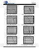
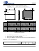
11.PACKAGE DIMENSIONS
(Unless otherwise specified, linear tolerance is ±0.05 mm, and angular tolerance is ±2 deg.)
1. Controlling dimensions are in millimeters.
2. Unless otherwise specified tolerance: Linear ±0.05 mm, Angular ±2 deg.
3. Dimensioning and tolerances per ASME Y 14.5M-1994.
4. Dimension lead width applies to the plated terminal and is measured 0.15 mm and 0.30 mm from the
terminal tip.
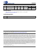
THERMAL CHARACTERISTICS
INCHES MILLIMETERS NOTE
Dim MIN NOM MAX MIN NOM MAX
A 0.01773 0.0197 0.45 - 0.50 1,3
A1 0.00000 0.00197 0.00 - 0.05 1,3
b 0.00591 0.00788 0.00985 0.15 0.20 0.25 1,3,4
e 0.01576 0.40 REF 1,3
D 0.19503 0.1970 0.19897 4.95 5.00 5.05 1,3
E 0.19503 0.1970 0.19897 4.95 5.00 5.05 1,3
D2 0.13593 0.1379 0.13987 3.45 3.50 3.55 1,3
E2 0.13593 0.1379 0.13987 3.45 3.50 3.55 1,3
L 0.01379 0.1576 0.01773 0.35 0.40 0.45 1,3
P1 0.00985 0.01182 0.01379 0.25 0.30 0.35 1,3
P2 0.00985 0.01182 0.01379 0.25 0.30 0.35 1,3
JEDEC #: MO-220
Controlling Dimension is Millimeters.
Parameter Symbol Min Typ Max Units
Junction to Ambient Thermal Impedance 2 Layer Board
4 Layer Board
θ
JA
θ
JA
-
-
68
28
-
-
°C/Watt
°C/Watt
PIN #1
CORNER
L
A
A1
e
b
D2
E2
P1
P1
E
D
1.50 REF
1.50 REF
P2
Pin #1 IDENTIFIER
LASER MARKING
P2
36L QFN (5 X 5 mm BODY) PACKAGE DRAWING (Note 2)