
Instruction Manual

DS773F1 15
CS42L55
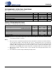
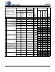
LINE OUTPUT CHARACTERISTICS
Test conditions (unless otherwise specified): Connections to the CS42L55 are shown in the “Typical Connection Diagram” on
page 10; Input test signal is a full-scale 997 Hz sine wave; All Supplies = VA, VCP Mode; GND = AGND = 0 V; T
A
= +25 °C;
Measurement bandwidth is 20 Hz to 20 kHz; Sample Frequency = 48 kHz; Test load R
L
= 3 kΩ, C
L
= 150 pF (see Figure 3 on
page 15).
Notes:
11. One-half LSB of triangular PDF dither is added to data.
12. The Analog Gain setting (refer to “Headphone Volume Control” on page 57 or “Line Volume Control” on
page 58) must be configured as indicated to achieve the specified output characteristics. High gain set-
tings at certain VA and VCP supply levels may cause clipping when the audio signal approaches full-
scale, maximum power output.
13. VCP settings lower than VA reduces the headroom of the headphone amplifier. As a result, the speci-
fied THD+N performance at full-scale output voltage and power may not be achieved.
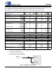
14. See Figure 3 and Figure 4 on page 15. Refer to “Parameter Definitions” on page 71.
VA = 2.5 V VA = 1.8 V
Parameter
(Note 11)
Min Typ Max Min Typ Max Unit
(+2 dB Analog Gain) (Note 12)
Dynamic Range
18 to 24-Bit A-weighted
unweighted
16-Bit A-weighted
unweighted
93
90
-
-
99
96
96
93
-
-
-
-
91
88
-
-
97
94
94
91
-
-
-
-
dB
dB
dB
dB
Total Harmonic Distortion + Noise
18 to 24-Bit 0 dB
-20 dB
-60 dB
16-Bit 0 dB
-20 dB
-60 dB
-
-
-
-
-
-
-84
-76
-36
-82
-74
-34
-78
-
-30
-
-
-
-
-
-
-
-
-
-86
-74
-34
-84
-72
-32
-80
-
-28
-
-
-
dB
dB
dB
dB
dB
dB
Full-scale Output Voltage (Note 13)
1.50•VA 1.58•VA 1.66•VA 1.50•VA 1.58•VA 1.66•VA V
PP
Other Characteristics
Interchannel Isolation
-90--90-dB
Interchannel Gain Mismatch
- 0.1 0.25 - 0.1 0.25 dB
Output Offset Voltage (Note 14) DAC to LINEOUT
-0.51.0-0.21.0mV
Gain Drift
- ±100 - - ±100 - ppm/°C
Output Impedance
- 100 - - 100 - Ω
AC-Load Resistance (R
L
) (Note 14)
3--3--kΩ
Load Capacitance (C
L
) (Note 14)
- - 150 - - 150 pF
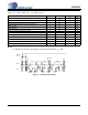
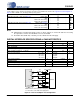
Test Load
LINEOUTx
GND/AGND
C
L
=150 pF
LINEREF
R
L
=3 kΩ
Measurement
Device
-
+
Test Load
HPOUTx
GND/AGND
C
L
=150 pF
0.1 μF
33 Ω
HPREF
R
L
=16 Ω or
3 k
Ω
Measurement
Device
-
+
Figure 3. HP Output Test Configuration Figure 4. Line Output Test Configuration