
Instruction Manual

12 DS773F1
CS42L55
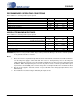
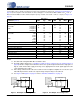
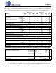
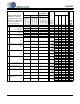
ANALOG INPUT CHARACTERISTICS
Test Conditions (unless otherwise specified): Connections to the CS42L55 are shown in the Figure 1. "Typical Connection Dia-
gram" on page 10; Input is a 1 kHz sine wave through the passive input filter, PGA = 0 dB; All Supplies = VA;
GND = AGND = 0 V; T
A
=+25°C; Measurement bandwidth is 20 Hz to 20 kHz. Sample Frequency = 48 kHz.
4. Referred to the typical full-scale voltage. Applies to all THD+N and Dynamic Range values in the table.
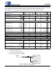
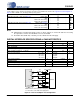
5. See test figure shown below.
6.
SDOUT Code with HPFx=1;HPFRZx=0.
7. Measured between AINxx and AGND.
VA = 2.5 V VA = 1.8 V
Parameter
(Note 4)
Min Typ Max Min Typ Max Unit
Analog In to ADC (PGA bypassed)
Dynamic Range A-weighted
unweighted
89
86
95
92
-
-
86
83
92
89
-
-
dB
dB
Total Harmonic Distortion + Noise -1 dBFS
-20 dBFS
-60 dBFS
-
-
-
-85
-72
-32
-79
-
-26
-
-
-
-85
-69
-29
-79
-
-23
dB
dB
dB
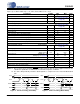
Analog In to PGA to ADC
Dynamic Range
PGA Setting: 0 dB A-weighted
unweighted
88
85
94
91
-
-
85
82
91
88
-
-
dB
dB
PGA Setting: +12 dB A-weighted
unweighted
81
78
87
84
-
-
78
75
84
81
-
-
dB
dB
Total Harmonic Distortion + Noise
PGA Setting: 0 dB -1 dBFS
-60 dBFS
-
-
-87
-31
-81
-25
-
-
-85
-28
-79
-22
dB
dB
PGA Setting: +12 dB -1 dBFS
- -83 -77 - -81 -75 dB
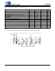
Common Mode Rejection (Note 5)
-40- -40-dB
DC Accuracy
Interchannel Gain Mismatch
- 0.2 - - 0.2 - dB
Gain Drift
- ±100 - - ±100 - ppm/°C
Offset Error (Note 6)
- 352 - - 352 - LSB
Input
Interchannel Isolation (1 kHz)
-90- -90-dB
HP Amp to Analog Input Isolation R
L
= 10 kΩ
R
L
= 16 Ω
-
-
90
83
-
-
-
-
90
83
-
-
dB
dB
Full-scale Input Voltage ADC
PGA (0 dB)
PGA (+12 dB)
0.76•VA
0.78•VA
0.80•VA
0.82•VA
0.198•VA
0.84•VA
0.86•VA
0.76•VA
0.78•VA
0.80•VA
0.82•VA
0.198•VA
0.84•VA
0.86•VA
Vpp
Vpp
Vpp
Input Impedance (Note 7) ADC
PGA
-
-
60
40
-
-
-
-
60
40
-
-
kΩ
kΩ
100 mV
PP
,
25 Hz
100 Ω
1 μF
AINxA
AINxREF
Figure 2. CMRR Test Configuration