
User Manual
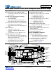


Table Of Contents
- 1. Pin Descriptions
- 2. Typical Connection Diagram
- 3. Characteristic and Specifications
- Recommended Operating Conditions
- Absolute Maximum Ratings
- Analog Input Characteristics
- ADC Digital Filter Characteristics
- Analog Output Characteristics
- Analog Passthrough Characteristics
- PWM Output Characteristics
- Headphone Output Power Characteristics
- Line Output Voltage Level Characteristics
- Combined DAC Interpolation and onChip Analog FIlter Response
- Switching Specifications - Serial Port
- Switching Specifications - I²C Control Port
- DC Electrical Characteristics
- Digital Interface Specifications and Characteristics
- Power Consumption
- 4. Applications
- 4.1 Overview
- 4.2 Analog Inputs
- 4.3 Analog Outputs
- 4.4 Analog In to Analog Out Passthrough
- 4.5 PWM Outputs
- 4.6 Serial Port Clocking
- 4.7 Digital Interface Formats
- 4.8 Initialization
- 4.9 Recommended Power-up Sequence
- 4.10 Recommended Power-Down Sequence
- 4.11 Required Initialization Settings
- 4.12 Control Port Operation
- 5. Register Quick Reference
- 6. Register Description
- 6.1 Chip I.D. and Revision Register (Address 01h) (Read Only)
- 6.2 Power Control 1 (Address 02h)
- 6.3 Power Control 2 (Address 03h)
- 6.4 Power Control 3 (Address 04h)
- 6.5 Clocking Control (Address 05h)
- 6.6 Interface Control 1 (Address 06h)
- 6.7 Interface Control 2 (Address 07h)
- 6.8 Input x Select: ADCA and PGAA (Address 08h), ADCB and PGAB (Address 09h)
- 6.9 Analog and HPF Control (Address 0Ah)
- 6.10 ADC HPF Corner Frequency (Address 0Bh)
- 6.11 Misc. ADC Control (Address 0Ch)
- 6.12 Playback Control 1 (Address 0Dh)
- 6.13 Miscellaneous Controls (Address 0Eh)
- 6.14 Playback Control 2 (Address 0Fh)
- 6.15 MICx Amp Control:MIC A (Address 10h) and MIC B (Address 11h)
- 6.16 PGAx Vol. and ALCx Transition Ctl.: ALC, PGA A (Address 12h) and ALC, PGA B (Address 13h)
- 6.17 Passthrough x Volume: PASSAVOL (Address 14h) and PASSBVOL (Address 15h)
- 6.18 ADCx Volume Control: ADCAVOL (Address 16h) and ADCBVOL (Address 17h)
- 6.19 ADCx Mixer Volume: ADCA (Address 18h) and ADCB (Address 19h)
- 6.20 PCMx Mixer Volume: PCMA (Address 1Ah) and PCMB (Address 1Bh)
- 6.21 Beep Frequency and On Time (Address 1Ch)
- 6.22 Beep Volume and Off Time (Address 1Dh)
- 6.23 Beep and Tone Configuration (Address 1Eh)
- 6.24 Tone Control (Address 1Fh)
- 6.25 Master Volume Control: MSTA (Address 20h) and MSTB (Address 21h)
- 6.26 Headphone Volume Control: HPA (Address 22h) and HPB (Address 23h)
- 6.27 Speaker Volume Control: SPKA (Address 24h) and SPKB (Address 25h)
- 6.28 ADC and PCM Channel Mixer (Address 26h)
- 6.29 Limiter Control 1, Min/Max Thresholds (Address 27h)
- 6.30 Limiter Control 2, Release Rate (Address 28h)
- 6.31 Limiter Attack Rate (Address 29h)
- 6.32 ALC Enable and Attack Rate (Address 2Ah)
- 6.33 ALC Release Rate (Address 2Bh)
- 6.34 ALC Threshold (Address 2Ch)
- 6.35 Noise Gate Control (Address 2Dh)
- 6.36 Status (Address 2Eh) (Read Only)
- 6.37 Battery Compensation (Address 2Fh)
- 6.38 VP Battery Level (Address 30h) (Read Only)
- 6.39 Speaker Status (Address 31h) (Read Only)
- 6.40 Charge Pump Frequency (Address 34h)
- 7. Analog Performance Plots
- 8. Example System Clock Frequencies
- 9. PCB Layout Considerations
- 10. ADC and DAC Digital Filters
- 11. Parameter Definitions
- 12. Package Dimensions
- 13. Ordering Information
- 14. References
- 15. Revision History

2 DS680F2
CS42L52
3/1/13
System Features
12, 24, and 27 MHz Master Clock Support in
Addition to Typical Audio Clock Rates
High-performance 24-bit Converters
– Multi-bit Delta-Sigma Architecture
– Very Low 64Fs Oversampling Clock Reduces
Power Consumption
Low-power Operation
– Stereo Analog Passthrough: 10 mW @ 1.8 V
– Stereo Playback: 14 mW @ 1.8 V
– Stereo Rec. and Playback: 23 mW @ 1.8 V
Variable Power Supplies
– 1.8 V to 2.5 V Digital and Analog
– 1.6 V to 5 V Class D Amplifier
– 1.8 V to 2.5 V Headphone Amplifier
– 1.8 V to 3.3 V Interface Logic
Power-down Management
– ADC, DAC, CODEC, MIC Pre-Amplifier, PGA,
Headphone Amplifier, Speaker Amplifier
Analog and Digital Routing/Mixes:
– Line/Headphone Out = Analog In (ADC
Bypassed)
– Line/Headphone/Speaker
Out = ADC + Digital In
– Digital Out = ADC + Digital In
– Internal Digital Loopback
– Mono Mixes
Flexible Clocking Options
– Master or Slave Operation
– High-impedance Digital Output Option (for easy
MUXing between CODEC and other data
sources)
– Quarter-speed Mode - (i.e. allows 8 kHz Fs
while maintaining a flat noise floor up to 16 kHz)
– 4 kHz to 96 kHz Sample Rates
I²C™ Control Port Operation
Headphone/Speaker Detection Input
Pop and Click Suppression
Applications
Digital Voice Recorders, Digital Cameras, and
Camcorders
PDA’s
Personal Media Players
Portable Game Consoles
General Description
The CS42L52 is a highly integrated, low-power stereo CO-
DEC with headphone and Class D speaker amplifiers. The
CS42L52 offers many features suitable for low-power, porta-
ble system applications.
The ADC input path allows independent channel control of a
number of features. Input summing amplifiers mix and select
line-level and/or microphone-level inputs for each channel.
The microphone input path includes a selectable programma-
ble-gain pre-amplifier stage and a low-noise MIC bias voltage
supply. A PGA is available for line or microphone inputs and
provides analog gain with soft-ramp and zero-cross transi-
tions. The ADC also features a digital volume control with soft
ramp transitions. A programmable ALC and Noise Gate mon-
itor the input signals and adjust the volume levels
appropriately. To conserve power, the ADC may be bypassed
while still allowing full analog volume control.
The DAC output path includes a digital signal processing en-
gine with various fixed-function controls. Tone Control
provides bass and treble adjustment of four selectable corner
frequencies. The Digital Mixer provides independent volume
control for both the ADC output and PCM input signal paths,
as well as a master volume control. Digital Volume controls
may be configured to change on soft-ramp transitions while
the analog controls can be configured to occur on every zero
crossing. The DAC also includes de-emphasis, limiting func-
tions and a BEEP generator, delivering tones selectable
across a range of two full octaves.
The stereo headphone amplifier is powered from a separate
positive supply and the integrated charge pump provides a
negative supply. This allows a ground-centered, analog output
with a wide signal swing and eliminates external DC-blocking
capacitors.
The Class D stereo speaker amplifier does not require an
external filter and provides the high-efficiency amplification re-
quired by power-sensitive portable applications. The speaker
amplifier may be powered directly from a battery while the in-
ternal DC supply monitoring and compensation provides a
constant gain level as the battery’s voltage decays.
In addition to its many features, the CS42L52 operates from a
low-voltage analog and digital core making it ideal for portable
systems that require extremely low power consumption in a
minimal amount of space.
The CS42L52 is available in a 40-pin QFN package in Com-
mercial (-40 to +85 °C) grade. The CS42L52 Customer
Demonstration board is also available for device evaluation
and implementation suggestions. Refer to “Ordering Informa-
tion” on page 81 for complete ordering information.