
User guide

52 DS679F1
CS42L51
6.4 Interface Control (Address 04h)
SDOUT to SDIN Loopback (SDOUT->SDIN)
Default: 0
0 - Disabled; SDOUT internally disconnected from SDIN
1 - Enabled; SDOUT internally connected to SDIN
Function:
Internally loops the signal on the SDOUT pin to SDIN.
Master/Slave Mode (M/S)
Default: 0
0 - Slave
1 - Master
Function:
Selects either master or slave operation for the serial port.
DAC Digital Interface Format (DAC_DIF[2:0])
Default = 000
Function:
Selects the digital interface format used for the data in on SDIN. The required relationship between the
Left/Right clock, serial clock and serial data is defined by the Digital Interface Format and the options are
detailed in the section “Digital Interface Formats” on page 40.
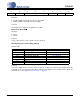
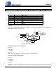
76543210
SDOUT->SDIN M/S
DAC_DIF2 DAC_DIF1 DAC_DIF0 ADC_I²S/LJ DIGMIX MICMIX
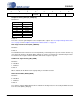
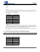
DAC_DIF[2:0] Description Figure
000 Left-Justified, up to 24-bit data 20 on page 41
001 I²S, up to 24-bit data 19 on page 40
010 Right-Justified, 24-bit data 21 on page 41
011 Right-Justified, 20-bit data 21 on page 41
100 Right-Justified, 18-bit data 21 on page 41
101 Right-Justified, 16-bit data 21 on page 41
110 Reserved -
100 Reserved -