
User guide

DS679F1 15
CS42L51
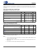
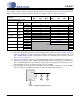
5. Referred to the typical full-scale voltage. Applies to all THD+N and Dynamic Range values in the table.
6. Measured between AINxx and AGND.
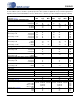
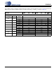
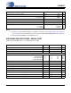
ADC DIGITAL FILTER CHARACTERISTICS
7. Response is clock-dependent and will scale with Fs. Note that the response plots (Figure 33 to Figure 41)
have been normalized to Fs and can be de-normalized by multiplying the X-axis scale by Fs. HPF param-
eters are for Fs = 48 kHz.
Parameter (Note 7) Min Typ Max Unit
Passband (Frequency Response) to -0.1 dB corner
0 - 0.4948 Fs
Passband Ripple
-0.09 - 0.17 dB
Stopband
0.6 - - Fs
Stopband Attenuation
33 - - dB
Total Group Delay
- 7.6/Fs - s
High-Pass Filter Characteristics (48 kHz Fs)
Frequency Response -3.0 dB
-0.13 dB
-
-
3.7
24.2
-
-
Hz
Hz
Phase Deviation @ 20 Hz
-10-Deg
Passband Ripple
- - 0.17 dB
Filter Settling Time
-10
5
/Fs 0 s