
Manual

CS4299-BQ
30
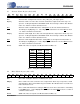
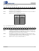
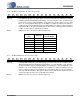
4.18 AC Mode Control Register (Index 5Eh)
DDM DAC Direct Mode. This bit controls the source to the line and alternate line output drivers. When
‘set’, the L/R DACs directly drive the line and alternate line outputs by bypassing the audio mix-
er. When ‘clear’, the audio mixer is the source for the line and alternate line outputs.
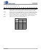
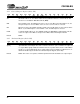
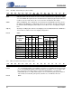
AMAP Audio Slot Mapping. This read/write bit controls whether the CS4299-BQ responds to the Co-
dec ID based slot mapping as outlined in the AC ’97 2.1 specification. The bit is shadowed in
the Extended Audio ID Register (Index 28h). Refer to Table8 for the slot mapping configura-
tions.
SM[1:0] Slot Map. The SM[1:0] bits define the Slot Mapping for the CS4299-BQ when the AMAP bit is
‘cleared’. Refer to Table8 for the slot mapping configurations.
Default 0080h
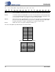
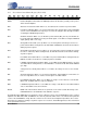
4.19 Misc. Crystal Control Register (Index 60h)
LOSM Loss of SYNC Mute Enable. The LOSM bit controls the loss of SYNC mute function. If this bit
is ‘set’, the CS4299-BQ will mute all analog outputs for the duration of loss of SYNC. If this
bit is ‘cleared’, the mixer will continue to function normally during loss of SYNC. The
CS4299-BQ expects to sample SYNC ‘high’ for 16 consecutive BIT_CLK periods and then
‘low’ for 240 consecutive BIT_CLK periods, otherwise loss of SYNC becomes true.
Default 0023h
D15 D14 D13 D12 D11 D10 D9 D8 D7 D6 D5 D4 D3 D2 D1 D0
0 0 0 0 0 0 0 DDM AMAP 0 SM1 SM0 0 0 0 0
Slot
Assignment
Mode
Codec ID Slot Map
AMAP
Slot Assignments
ID1 ID0 SM1 SM0
DAC,
SPDIF
ADC
L R L R
AMAP Mode 0 0 0 X X 1 3 4 3 4
AMAP Mode 1 0 1 X X 1 3 4 3 4
AMAP Mode 2 1 0 X X 1 7 8 7 8
AMAP Mode 3 1 1 X X 1 6 9 6 9
Slot Map Mode 0 X X 0 0 0 3 4 3 4
Slot Map Mode 1 X X 0 1 0 5 6 5 6
Slot Map Mode 2 X X 1 0 0 7 8 7 8
Slot Map Mode 3 X X 1 1 0 9 10 9 10
Table 8. Slot Mapping
D15 D14 D13 D12 D11 D10 D9 D8 D7 D6 D5 D4 D3 D2 D1 D0
0 0 0 0 Reserved 0 0 Reserved 0 Reserved LOSM
30 DS319-BQPP2
CS4299-BQ